BMW X3 (F25) Service & Repair Manual: Front axle
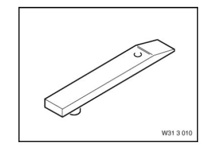
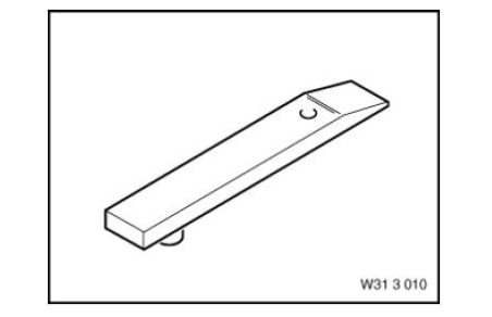
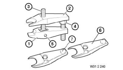
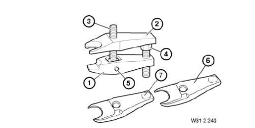
- Adapter
- Basic body
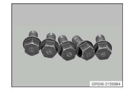
- Bolt
- Bush
- Device
- Extractor
- Fixture
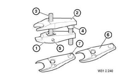
- Fork
- Gauge
- Holder
- Holding sleeve
- Insert
- Mandrel
- Measurement aid
- Pin
- Pin wrench
- Ring
- Screw
- Shaped part
- Socket waf 46
- Spindle
- Spring tensioner
- Synchronising key
- Tool
- Tool set
- Washer
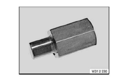
Adapter
Adapter AM
NOTE: Adapter M4 (Ø 96mm) in connection with adapter kit 2 (BMW), (81642155746), for removal and installation of wheel bearings, propeller shafts and drive flanges.
SI number
08 06 09 (544)
Adapter AM
NOTE: Adapter R7 (M24/Ø 87/95mm) in connection with adapter kit F03 (81 64 2 348 804) for installation and removal of wheel bearings, propeller shafts and drive shafts.
SI number
08 02 13 (900)
Adapter AM
NOTE: Adapter P5 (/Ø 45/82.5mm) in connection with wheel bearing adapter kit F30 (84mm, no longer in Catalogue) for installation and removal of wheel bearings, propeller shafts and drive shafts.
SI number
08 09 12 (873)
Adapter AM
NOTE: Adapter N1 (Ø 49mm) in connection with adapter kit 2 (BMW), (81 64 2 155 746), for removal and installation of wheel bearings, propeller shafts and drive flanges.
SI number
08 06 09 (544)
Adapter AM
NOTE: Adapter R6 (M24/Ø 63/75mm) in connection with adapter kit F30 (84mm wheel bearings) for installation and removal of wheel bearings, propeller shafts and drive shafts.
SI number
08 09 12 (873)
Adapter AM
NOTE: Adapter N4 (Ø 39mm) in connection with adapter kit 2 (BMW), (81 64 2 155 746), for removal and installation of wheel bearings, propeller shafts and drive flanges.
SI number
08 06 09 (544)
Adapter Mechanical tool
NOTE: (Adapter) For pulling off the taper roller bearings from the equalisation housing in the front axle differential
Adapter AM
NOTE: (take-up adapter for bore holes (2 x))
SI number
01 24 06 (309)
Adapter AM
NOTE: Adapter M2 (Ø 88mm) in connection with adapter kit 2 (BMW), (81 64 2 155 746), for removal and installation of wheel bearings, propeller shafts and drive flanges.
SI number
08 06 09 (544)
Adapter AM
NOTE: Adapter M8 for removal and installation of wheel bearings, propeller shafts and drive flanges.
SI number
08 06 09 (544)
Adapter AM
NOTE: Adapter P3 (Ø 39/72mm) in connection with adapter kit 2 (BMW), (81 64 2 155 746), for removal and installation of wheel bearings, propeller shafts and drive flanges.
SI number
08 06 09 (544)
Adapter AM
NOTE: Adapter R3 (M24/Ø 69/79mm) in connection with adapter kit 2 (BMW), (81 64 2 155 746), for removal and installation of wheel bearings, propeller shafts and drive flanges.
SI number
08 06 09 (544)
Adapter AM
NOTE: Adapter R8 (M24/Ø 74/83mm) in connection with adapter kit F03 (81642348804) for installation and removal of wheel bearings, propeller shafts and drive shafts.
SI number
08 02 13 (900)
Adapter AM
NOTE: Adapter P6 (/Ø 51/89mm) in connection with adapter kit F03 (81 64 2 348 804) for installation and removal of wheel bearings, propeller shafts and drive shafts.
SI number
08 02 13 (900)
Adapter AM
NOTE: Adapter P1 (Ø 45/85mm) in connection with adapter kit 2 (BMW), (81 64 2 155 746), for removal and installation of wheel bearings, propeller shafts and drive flanges.
SI number
08 06 09 (544)
Adapter AM
NOTE: Adapter P4 (Ø 42/75 mm) in combination with adapter kit 2 BMW (81 64 2 155 746) for removing and installing wheel bearings, output shafts and drive flanges.
SI number
08 06 09 (544)
Adapter AM
NOTE: Adapter Z1 to attach torque wrench. Used in connection with hydraulic cylinder, (81642156246), for removal and installation of wheel bearings, propeller shafts and drive flanges.
SI number
08 04 12 (797)
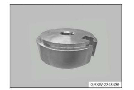
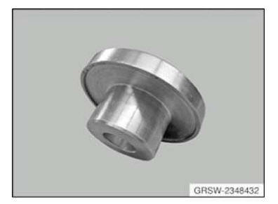
Adapter AM
NOTE: Adapter set F03 as a supplement to the hydraulic tool for removal and installation of wheel bearings, output shafts and drive flanges.
SI number
08 02 13 (900)
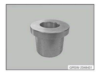
Consisting of:
- 2348430
- 2348432
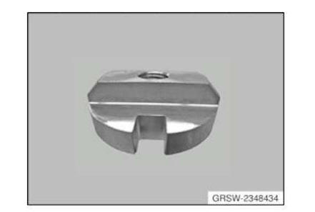
- 2348434
- 2348436
- 2348431
Adapter AM
NOTE: Adapter R4 (M24/Ø 64/75mm) in connection with adapter kit 2 (BMW), (81 64 2 155 746), for removal and installation of wheel bearings, propeller shafts and drive flanges.
SI number
08 06 09 (544)

Adapter AM
NOTE: Adapter R2 (M24 tapered) in connection with adapter kit 2 (BMW), (81 64 2 155 746), for removal and installation of wheel bearings, propeller shafts and drive flanges.
SI number
08 06 09 (544)
Adapter AM
NOTE: Adapter M6 (Ø 102/113mm) in connection with adapter kit 2 (BMW), (81 64 2 155 746), for removal and installation of wheel bearings, propeller shafts and drive flanges.
SI number
08 06 09 (544)
Adapter AM
NOTE: (take-up adapter U-section (2 x))
SI number
01 24 06 (309)
Adapter AM
NOTE: Adapter N5 (/Ø 51mm) in connection with adapter kit F03 (81642348804) for installation and removal of wheel bearings, propeller shafts and drive shafts.
SI number
08 02 13 (900)
Adapter AM
NOTE: Adapter H2 (tooth finder) in combination with adapter kit 1 BMW (81 64 2 155 745) for removal and installation of wheel bearings, output shafts and drive flanges.
SI number
08 06 09 (544)
NOTE: Adapter N2 (Ø 45mm) in connection with adapter kit 2 (BMW), (81 64 2 155 746), for removal and installation of wheel bearings, propeller shafts and drive flanges.
SI number
08 06 09 (544)
Adapter AM
NOTE: Adapter P2 (Ø 49/90mm) in connection with adapter kit 2 (BMW) and adapter kit 3 RR for removal and installation of wheel bearings, propeller shafts and drive flanges.
SI number
08 06 09 (544)
Adapter AM
NOTE: Adapter B1 in connection with adapter kit 1 (BMW), (81 64 2 155 745) and MINI adapter kit (81 64 2 294 517), for removal and installation of wheel bearings, propeller shafts and drive flanges.
SI number
08 06 09 (544)
Adapter AM
NOTE: Adapter R5 (M24/Ø 59/70mm) in connection with adapter kit 2 (BMW), (81 64 2 155 746), for removal and installation of wheel bearings, propeller shafts and drive flanges.
SI number
08 06 09 (544)
Adapter AM
NOTE: Adapter N3 (Ø 42mm) in connection with adapter kit 2 (BMW), (81 64 2 155 746), for removal and installation of wheel bearings, propeller shafts and drive flanges.
SI number
08 06 09 (544)
Adapter AM
NOTE: Adapter M5 (Ø 90mm) in connection with adapter kit 2 (BMW), (81 64 2 155 746), for removal and installation of wheel bearings, propeller shafts and drive flanges.
SI number
08 06 09 (544)
Adapter AM
NOTE: Adapter M1 (Ø 100/101mm) in connection with adapter kit 2 (BMW), (81 64 2 155 746), for removal and installation of wheel bearings, propeller shafts and drive flanges.
SI number
08 06 09 (544)
Adapter AM
NOTE: (take-up adapter for bore holes (2 x))
SI number
01 24 06 (309)
Adapter AM
NOTE: Adapter M3 (Ø 102mm) for installation and removal of wheel bearings, propeller shafts and drive shafts.
SI number
08 06 09 (544)
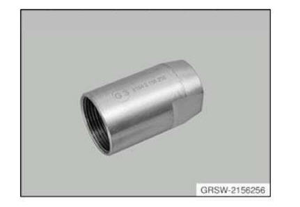
NOTE: Adapter G3 (M27x1.5/M20) in connection with adapter kit 1 (BMW), (81 64 2 155 745), for removal and installation of wheel bearings, propeller shafts and drive flanges.
SI number
08 06 09 (544)
Adapter Minimum set: Mechanical tools AM
NOTE: (Adapter feet) Series: E46
Storage Location
A7
Adapter AM
NOTE: (take-up adapter (2 x))
SI number
01 24 06 (309)
Adapter AM
NOTE: Adapter E2 (M24) in connection with adapter kit 1 (BMW), (81 64 2 155 745), for removal and installation of wheel bearings, propeller shafts and drive flanges.
SI number
08 06 09 (544)
Adapter AM
NOTE: Adapter G2 (M24x1.5/M20) in connection with adapter kit 1 (BMW), (81 64 2 155 745), for removal and installation of wheel bearings, propeller shafts and drive flanges.
SI number
08 06 09 (544)
Adapter AM
NOTE: Adapter for workshop jack for screwing-on at existing 120 mm hole-circle diameter and new 112 mm hole-circle diameter on wheel hub. Contour-graphic silhouette foil is included in delivery specification.
Storage Location
B74
A74
SI number
01 21 14 (110)
Adapter AM
NOTE: Adapter R1 (M24/Ø 77/82mm) in connection with adapter kit 2 (BMW), (81 64 2 155 746), for removal and installation of wheel bearings, propeller shafts and drive flanges.
SI number
08 06 09 (544)
Adapter AM
NOTE: Adapter G1 (M22x1.5/M20) in connection with adapter kit 1 (BMW), (81 64 2 155 745), for removal and installation of wheel bearings, propeller shafts and drive flanges.
SI number
08 06 09 (544)
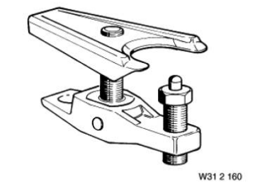
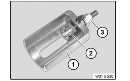
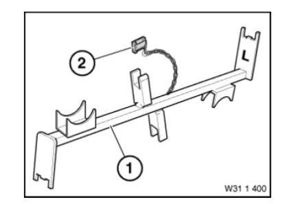
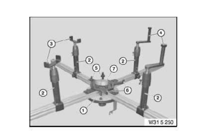
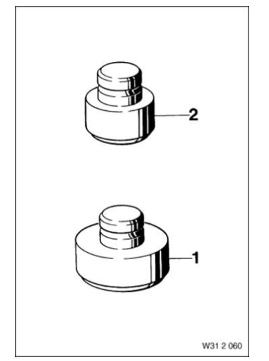
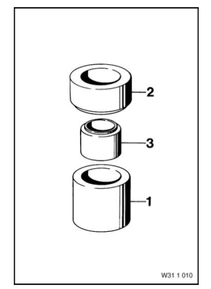
Basic body
Basic body AM
NOTE: (Basic body) No longer available separately, only via special tool set 31 5 250 (83 30 0 495 567)
SI number
01 24 06 (309)
Basic body AM
Basic body AM
BEARING
Bearing AM
NOTE: (Thrust bearing)
BELT
Belt AM
NOTE: (Tensioning strap)
SI number
01 24 06 (309)
Bolt
Bolt AM
Replaced by: 83300492053
NOTE: Replaced by 32 3 090. (0 492 053)
Bolt Mechanical tool
NOTE: (drive pin) For radial gears in the front axle differential for checking the coefficient of friction
BRIDGE
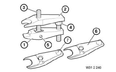
Bridge Minimum set: Mechanical tools AM
NOTE: (Support bridge) All-wheel drive vehicles, series: E30, E36, E46, E85 Discontinued, only available via complete tool
Storage Location
B7
Bridge AM
NOTE: (Measuring bridge)
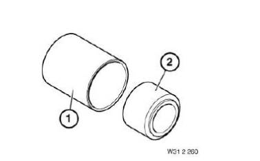
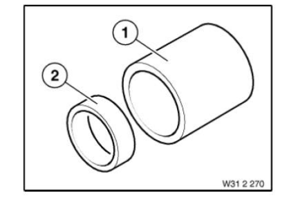
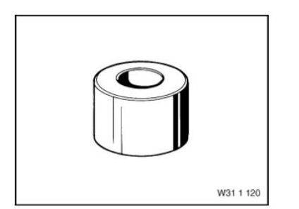
Bush
Bush AM
NOTE: For installing the rubber mount in the front axle support - series: E12
Bush AM
NOTE: (Bush) For installing the rubber mount in the front axle support and thrust piece, for removing and installing the rubber mount in the wishbones

Bush Mechanical tool
NOTE: (impact bush) For fitting the radial sealing ring to the drive flange of the front axle differential
Storage Location
X7
SI number
01 04 93 (664)
Bush AM
NOTE: (Bush) Deletion, only available via tool set
Bush AM
NOTE: (Bush) For removing the rubber mount from the front axle support, for removing and installing the rubber mount in the wishbones and for press-fitting the taper roller bearing of the rear axle differential housing
NOTE: (Slip bush) For installing the rubber mount in the front axle support

NOTE: (Pressure bush)
NOTE: (Threaded bush)
CLIP
Clip Mechanical tool
NOTE: (mounting fixture) For the front axle differential
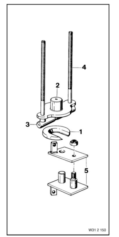
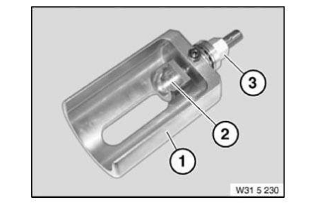
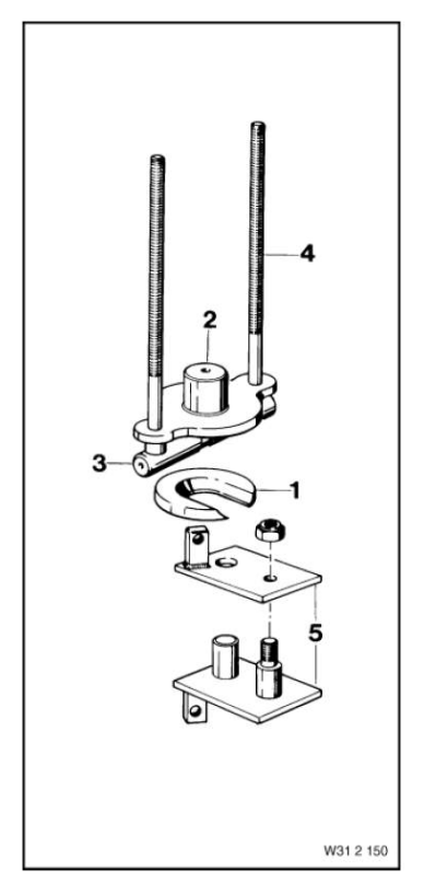
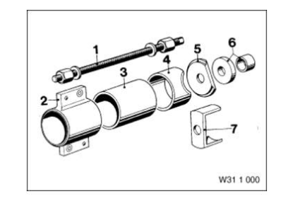
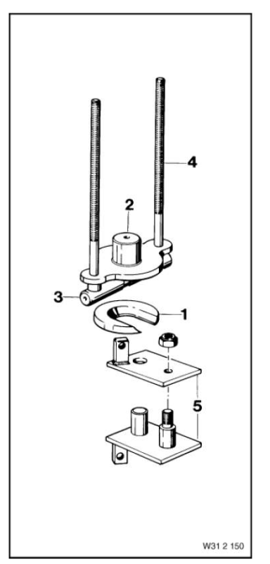
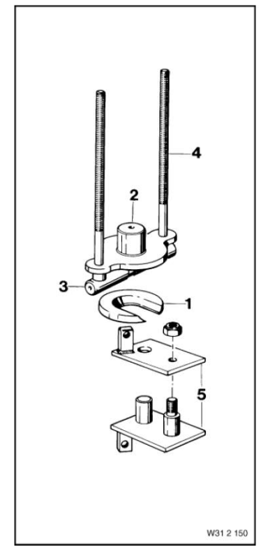
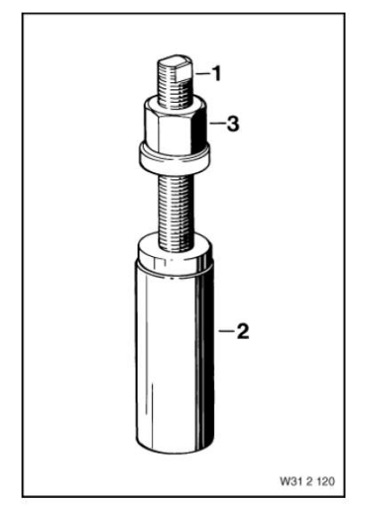
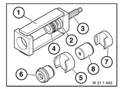
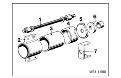
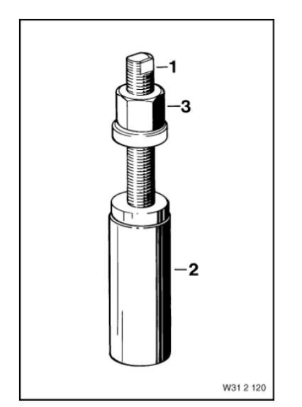
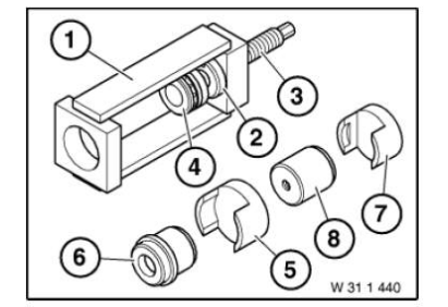
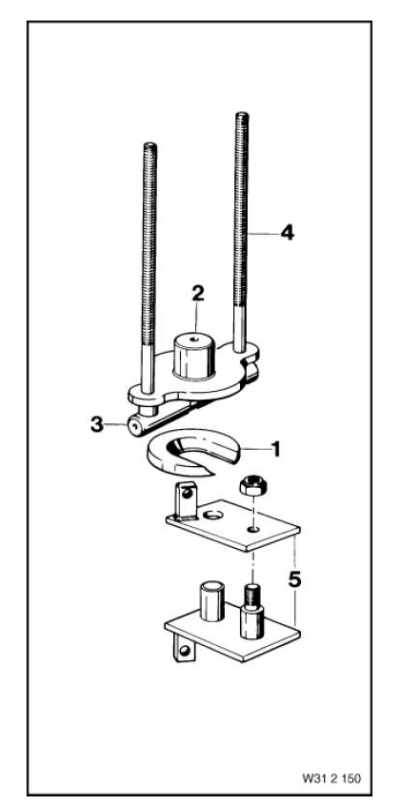
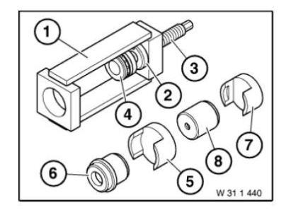
Device
Device AM
NOTE: For drawing spring strut into swivel bearing seat.
Storage Location
B72
SI number
01 13 07 (387)
Consisting of:
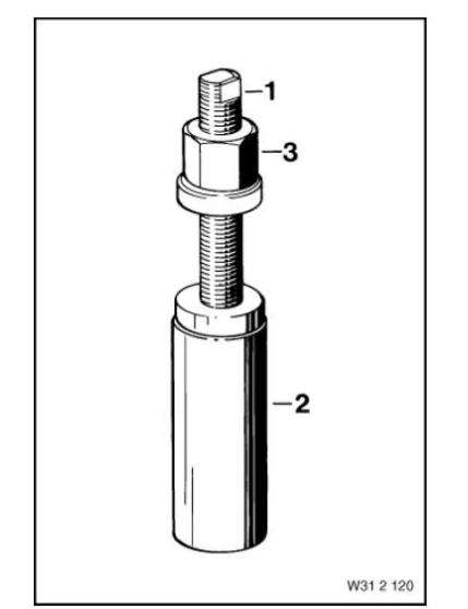
1. Basic body
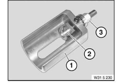
2. Spindle
NOTE: (Spindle M10 with fixture) discontinued, available as part of set of special tools only
3. Nut
NOTE: (Nut with bearing) Can no longer be ordered separately. Only available as part of set 31 2 120 = 83 30 0 491 909.
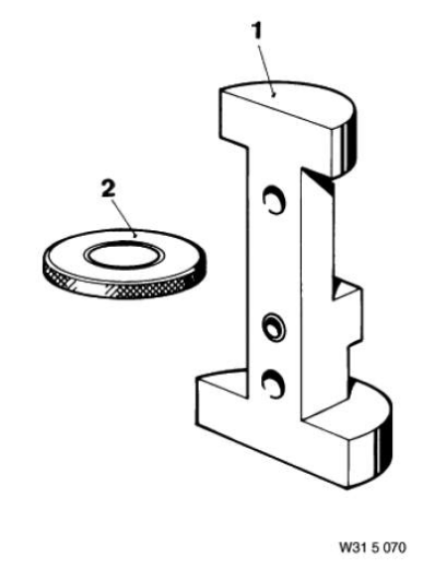
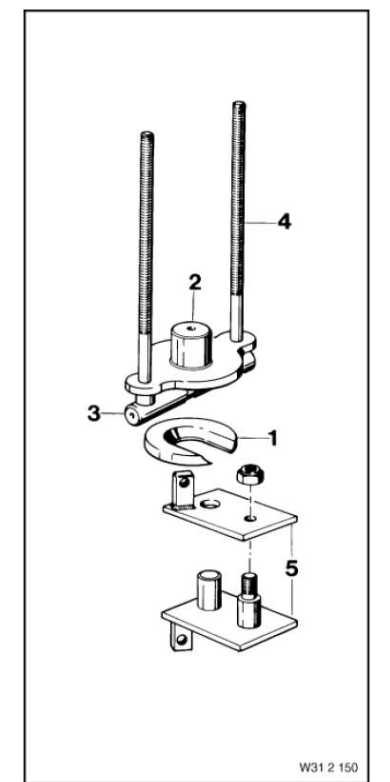
Device AM
NOTE: For determining the installation dimension at the bevel drive pinion in the front axle differential
Consisting of:
1. Bridge
NOTE: (Measuring bridge)
2. Washer
NOTE: (Measuring disc 7 mm)
Device Mechanical tool
NOTE: (Device) to tension the spring struts when removing and installing - not required for 31 3 120
Device Mechanical tool
NOTE: For removing spring strut guide joints from left or right steering stub (interchangeable) (E30/C)
Storage Location
Y5
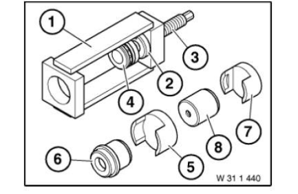
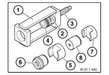
Device AM
NOTE: For removing and installing the rubber mount in the front axle support and in the wishbones and for press-fitting the taper roller bearing onto the differential case of the rear axle differential.
Storage Location
Z5
Consisting of:
1. Spindle
NOTE: With 2 nuts and 2 washers
2. Bush
NOTE: (Slip bush) For installing the rubber mount in the front axle support
3. Bush
NOTE: (Bush) For removing the rubber mount from the front axle support, for removing and installing the rubber mount in the wishbones and for press - fitting the taper roller bearing of the rear axle differential housing
4. Pipe
NOTE: (Support tube) For installing the rubber mount in the front axle support - series: E12
5. Washer
NOTE: (Flanged washer) For centring of threaded spindle and as a support disc for removing and installing the rubber mount in the front axle support and in the wishbones - series: E12
6. Synchronising key
NOTE: For removing and installing the rubber mount in the front axle support - series: E12
7. Bush
NOTE: For installing the rubber mount in the front axle support - series: E12
8. Bush
NOTE: (Bush) For installing the rubber mount in the front axle support and thrust piece, for removing and installing the rubber mount in the wishbones
9. Bush
NOTE: (Bush) Deletion, only available via tool set
Device Mechanical tool
NOTE: For pressing off and applying the wheel hub sealing caps - model year: up to 82
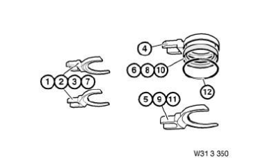
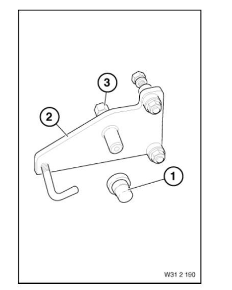
Device Minimum set: Mechanical tools AM
NOTE: For removing and installing rubber mount in front wishbone
Storage Location
A7
Consisting of:
8 = Adapter
NOTE: (Adapter feet) Series: E46
1 = Plate
NOTE: Series: E30, E36, E46, E85
2 = Synchronising key
NOTE: Series: E30, E36, E46, E85
3 = Holder
NOTE: (Counter support) Series: E30, E36, E46, E85
4 = Spindle
NOTE: Spindle (1 piece) series: E30, E36, E46, E85
5 = Bridge
NOTE: (Support bridge) All-wheel drive vehicles, series: E30, E36, E46, E85 Discontinued, only available via complete tool
6 = Holder
NOTE: (Counter support, diameter 79 mm) For mounting the rubber mount on the wishbone, series: E46 Discontinued, only available via complete tool 0 491 918.
7 = Synchronising key
NOTE: (Synchronizing key, diameter 79 mm) For mounting the rubber mount on the wishbone, series: E46
Device AM
Replaced by: 83300492053
NOTE: For pressing the wishbone off the spring strut/Replaced by 32 3 090 (0 492 053)
Consisting of:
1. Spindle
NOTE: Replaced by 32 3 090. (0 492 053)
2. Bolt
NOTE: Replaced by 32 3 090. (0 492 053)
Device AM
Replaced by: 83300492053
NOTE: For pressing the drive flange out of the wheel bearing Replaced by 33 4 200. (0 492 053)
Consisting of:
1. Synchronising key
NOTE: Discontinuation and replaced by 33 4 200 (0 492 053)
2. Plate
NOTE: Discontinuation and replaced by 33 4 200 (0 492 053)
3. Spindle
NOTE: Discontinuation and replaced by 33 4 200 (0 492 053)
Device Mechanical tool
NOTE: For pressing off the wishbones from the spring strut
SI number
01 04 92 (487)
Device AM
NOTE: For removing and installing wheel control joints
SI number
01 09 96 (094)
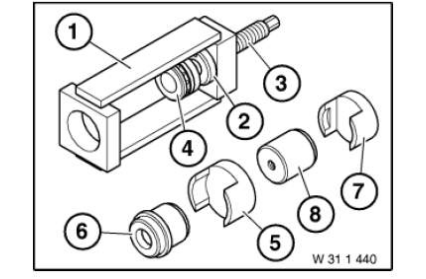
Consisting of:
1. Basic body
2. Bush
NOTE: (Threaded bush)
3. Spindle
4. Bearing
NOTE: (Thrust bearing)
5. Synchronising key
NOTE: (Thrust piece) For removing
6. Synchronising key
NOTE: For removing
7. Synchronising key
NOTE: For installing
8. Pipe
NOTE: (Guide tube) For installing
Device Mechanical tool
NOTE: (Extractor tool) For pressing off the leading link from the track rod arm
Storage Location
Y6
SI number
01 06 88 (964)
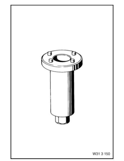
Device AM
NOTE: For installing the wheel bearing unit at the front
Storage Location
Y9
Consisting of:
1. Spindle
NOTE: With guide sleeve Discontinued, only available via complete tool
2. Bush
NOTE: (Pressure bush)
3. Nut
NOTE: (Nut with bearing) Can no longer be ordered separately. Only available as part of set 31 2 120 = 83 30 0 491 909.
Device AM
NOTE: Device A1 in connection with adapter kit 1 (BMW), (81 64 2 155 745), for removal and installation of wheel bearings, propeller shafts and drive flanges.
SI number
08 06 09 (544)
Device Mechanical tool
NOTE: For pulling out the trailing links, left and right wishbones and leading links
Storage Location
X5
Device Mechanical tool
Replaced by: 83300492436
NOTE: For pressing the drive flange out of the front wheel bearing Replaced by 33 4 200. (0 492 436)
EXTENSION
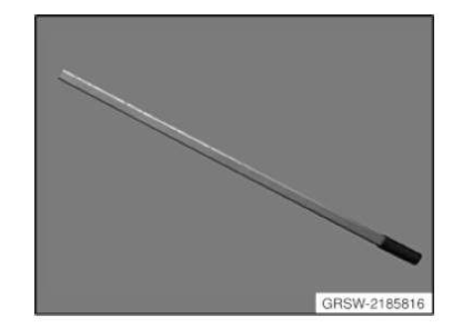
Extension AM
NOTE: Extension lever (extension) to loosen and tighten the screw connections on wishbone and tension strut in conjunction with special tools set 81642185817 (ring spanner).
SI number
08 04 10 (656)
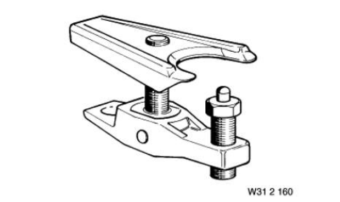
Extractor
Extractor Mechanical tool
NOTE: For removing the track rod from the front axle
Storage Location
C41
SI number
01 03 00 (554)
Extractor Minimum set: Mechanical tools AM
NOTE: For removing the output shafts from the front axle differential --> E46/16
Storage Location
A41
B41
SI number
01 07 00 (576)
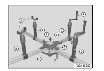
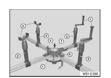
Fixture
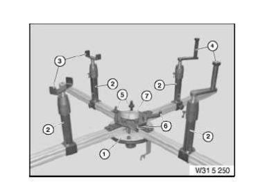
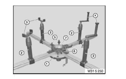
Fixture AM
In conjunction with: UNIVERSAL HYDRAULIC LIFTING EQUIPMENT 81222219012
NOTE: (universal axle take-up) For accommodating all front and rear axles when removing and installing.
SI number
01 24 06 (309)
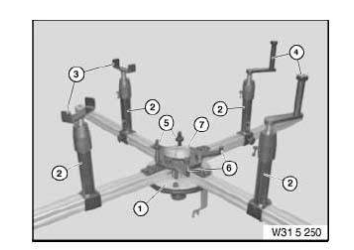
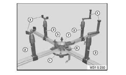
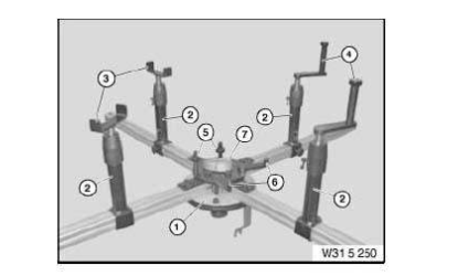
Consisting of:
1. Basic body
NOTE: (Basic body) No longer available separately, only via special tool set 31 5 250 (83 30 0 495 567)
2. Support
NOTE: (Telescope supports) 4 pieces, no longer available separately, only via special tool set 31 5 250 (83 30 0 495 567)
3. Adapter
NOTE: (take-up adapter U-section (2 x))
4. Adapter
NOTE: (take-up adapter (2 x))
5. Adapter
NOTE: (take-up adapter for bore holes (2 x))
6. Adapter
NOTE: (take-up adapter for bore holes (2 x))
7. Belt
NOTE: (Tensioning strap)
Fixture Mechanical tool
NOTE: For securing wheel hub when removing and installing spring strut.
Storage Location
A19
SI number
01 23 05 (224)
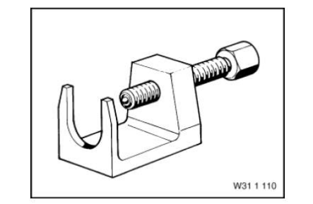
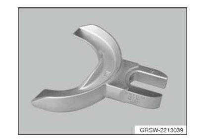
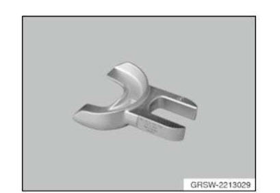
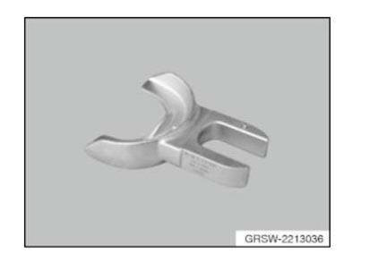
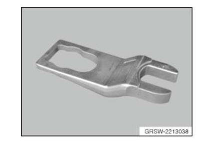
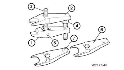
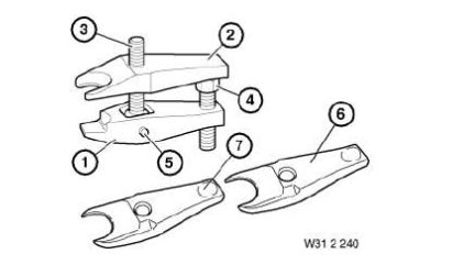
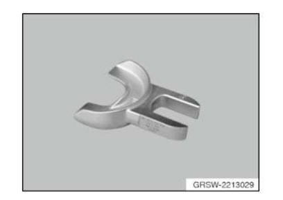
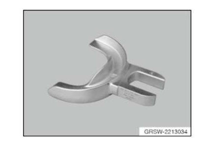
Fork
Fork Mechanical tool
NOTE: (Press-off fork) For pressing the output shaft off of the front axle differential (all-wheel drive vehicles)
SI number
01 17 05 (212)
Fork AM
NOTE: (Separating fork)
Fork AM
NOTE: (Separating fork) for separating the conical seat at the wheel guide joint from the wheel carrier - delivered for campaign due to warranty/introduced in 6/96 as set of special tools
SI number
01 09 96 (094)
Consisting of:
1. Fork
NOTE: (Separating fork)
2. Guard
NOTE: (Protective gloves)
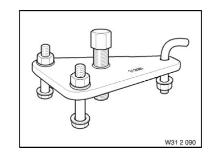
Gauge
Gauge AM
NOTE: (test gauge) For checking the trailing link for distortion when repairing accident damage
SI number
01 23 97 (246)
Consisting of:
1. Gauge
NOTE: (test gauge) For right and left-hand trailing link
2. Shaped part
NOTE: (shaped part) For trailing links without date stamp, up to model year 5/96
Gauge AM
NOTE: (test gauge) For right and left-hand trailing link
Gauge Minimum set: Mechanical tools AM
NOTE: For positioning the support bearing.
SI number
01 19 10 (674)
GUARD
Guard AM
NOTE: (Protective gloves)
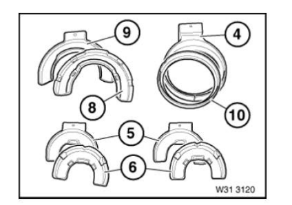
Holder
Holder Minimum set: Mechanical tools AM
NOTE: (Counter support) Series: E30, E36, E46, E85
Storage Location
A7
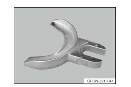
Holder AM
Replaced by: 83302213041
NOTE: (Spring retainer) As of 08/2011, available under new item number 83 30 2 213 041
SI number
01 16 11 (738)
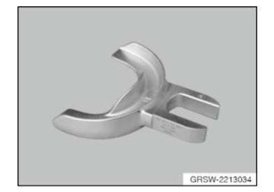
Holder AM
Replaced by: 83302213034
NOTE: (Spring retainer) As of 08/2011, available under new item number 83 30 2 213 034
SI number
01 16 11 (738)
Holder AM
NOTE: (Spring retainer (2 pieces)) With protective insert 31 3 326 - Series: E38 rear, E39 Saloon rear
Holder AM
Replaced by: 83302213039
NOTE: (Spring retainer) As of 08/2011, available under new item number 83 30 2 213 039
SI number
01 16 11 (738)
Holder AM
Replaced by: 83300493560
NOTE: (Spring retainer (2 pieces)) With protective insert 31 3 127 - Model series: E32, E34 Touring, E36 Discontinuation and replaced by 31 3 350. (0 493 560)
Holder AM
Replaced by: 83300493560
NOTE: (Spring retainer) With protective insert 31 3 128 - model series: E46 Discontinuation and replaced by 31 3 350. (0 493 560)
Holder Minimum set: Mechanical tools AM
NOTE: (Counter support, diameter 79 mm) For mounting the rubber mount on the wishbone, series: E46 Discontinued, only available via complete tool 0 491 918.
Storage Location
B7
Holder AM
Replaced by: 83302213026
NOTE: Clamping plate (1 piece), available under new order number 83 30 2 213 026 as of July 2011
SI number
01 16 11 (738)
Holder AM
Replaced by: 83302213024
NOTE: Clamping plate (1 piece), available under new order number 83 30 2 213 024 as of July 2011
SI number
01 16 11 (738)
Holder AM
NOTE: (Spring retainer) With protective insert 31 3 332 - Series: E46
Holder AM
Replaced by: 83300493560
NOTE: (Spring retainer (2 pieces)) With protective insert 31 3 126 - model series: E38 rear, E39 Saloon rear Discontinuation and replaced by 31 3 350. (0 493 560)
Holder AM
Replaced by: 83302213029
NOTE: Clamping plate (1 piece) As of 08/2011, available under new item number 83 30 2 213 029
SI number
01 16 11 (738)
Holder AM
NOTE: (Spring retainer (2 pieces)) With protective insert 31 3 328 - Series: E31, E38, E39 front high (2x) and basis (1x)/model: Z3, Z3coupe
Holder AM
Replaced by: 83300493560
NOTE: (Spring retainer (2 pieces)) With protective insert 31 3 128 - Model series: E31, E38, E39 front high (2x) and basic version (1x) Discontinuation and replaced by 31 3 350. (0 493 560)
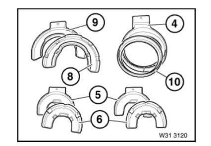
Holder AM
NOTE: (Spring retainer (2 pieces)) With protective insert 31 3 327 - Series: E32, E34, E36
Holder AM
Replaced by: 83302213036
NOTE: (Spring retainer) As of 08/2011, available under new item number 83 30 2 213 036
SI number
01 16 11 (738)
Holder AM
Replaced by: 83302250167
NOTE: (Spring retainer) As of 08/2011, delivery under new item number 83 30 2 250167= completely new set with newly defined content
Storage Location
Individual
SI number
01 16 11 (738)
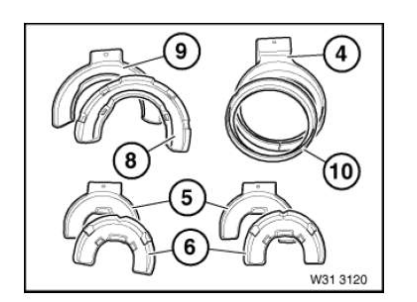
Consisting of:
7 = Holder
NOTE: (Spring retainer) As of 08/2011, available under new item number 83 30 2 213 036
8 = Ring
NOTE: (Insertion ring) As of 08/2011, available under new item number 83 30 2 213 033
9 = Ring
NOTE: (Spring retainer ring) As of 08/2011, available under new item number 83 30 2 213 038
10 = Holder
NOTE: (Spring retainer) As of 08/2011, available under new item number 83 30 2 213 039
11 = Holder
NOTE: (Spring retainer) As of 08/2011, available under new item number 83 30 2 213 041
1 = Holder
NOTE: Clamping plate (1 piece), available under new order number 83 30 2 213 024 as of July 2011
2 = Holder
NOTE: Clamping plate (1 piece), available under new order number 83 30 2 213 026 as of July 2011
3 = Holder
NOTE: Clamping plate (1 piece) As of 08/2011, available under new item number 83 30 2 213 029
4 = Ring
NOTE: (Spring retainer ring) As of 08/2011, available under new item number 83 30 2 213 031
5 = Holder
NOTE: (Spring retainer) As of 08/2011, available under new item number 83 30 2 213 034
6 = Ring
NOTE: (Centering ring) As of 08/2011, available under new item number 83 30 2 213 032
Holding sleeve
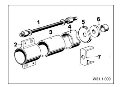
Holding sleeve AM
NOTE: (Pressure sleeve) For gripping the wishbones and for removing and installing the silence blocks in the leading link. Discontinued, can only be ordered using complete tool
Holding sleeve Minimum set: Mechanical tools AM
Replaced by: 83300491916
NOTE: (Pressure sleeve) For counter-holding/model series: E30 Replaced by 31 2 133.
(0 491 916)
Storage Location
B13
Holding sleeve Minimum set: Mechanical tools AM
NOTE: (Push sleeve) For removing and installing. Series: E53, E83
Storage Location
B13
Holding sleeve AM
NOTE: (Pressure sleeve) for counterholding, discontinued, available as part of set of special tools only
Holding sleeve Minimum set: Mechanical tools AM
NOTE: (Pressure sleeves) For removing and installing the rubber mount in the trailing link of the front axle
Storage Location
B13
SI number
01 12 95 (992)
Consisting of:
1. Holding sleeve
NOTE: (Pressure sleeve) for counterholding, discontinued, available as part of set of special tools only
2. Holding sleeve
NOTE: (Pressure sleeve) For removing and installing
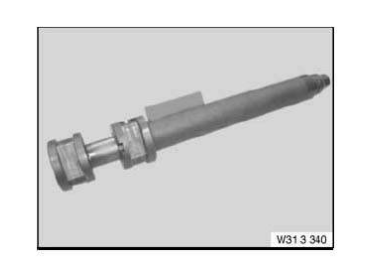
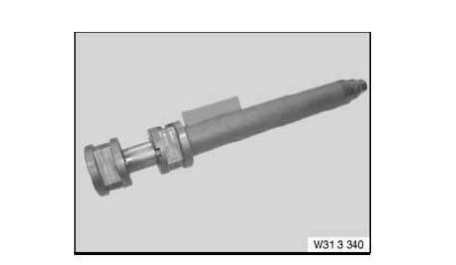
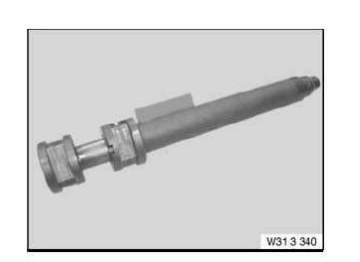
Holding sleeve AM
Replaced by: 83300493555
NOTE: (Centring sleeve) Internal thread M18x1.5 Replaced by 31 3 340 (0 493 555)
Holding sleeve Minimum set: Mechanical tools AM
NOTE: (Pressure sleeve) For pulling out and in/model series: E30 All-wheel drive vehicle, E34, E36, E46 Can no longer be ordered separately. Only available as part of set 31 2 130 = 83 30 0 491 913.
Storage Location
B13
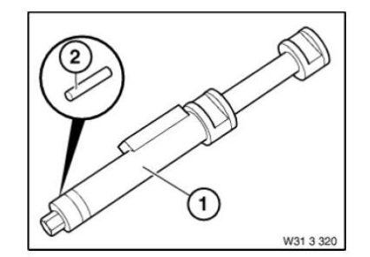
Holding sleeve AM
Replaced by: 83300493555
NOTE: (Centring sleeve) Internal thread M12x1.5 Replaced by 31 3 340 (0 493 555)
Holding sleeve AM
Replaced by: 83300493747
NOTE: (Pressure sleeve) For gripping the wishbones and for removing and installing the silence blocks in the leading link. Replaced by 31 1 054. (0 493 747)
Holding sleeve AM
NOTE: Sleeve C1 in connection with adapter kit 1 (BMW), (81 64 2 155 745) and MINI adapter kit (81 64 2 294 517), for removal and installation of wheel bearings, propeller shafts and drive flanges.
SI number
08 06 09 (544)
Holding sleeve Minimum set: Mechanical tools AM
NOTE: (Push sleeve) As counter support when removing and installing. Series: E38, E39, E83 For removing and installing rubber mounts in wishbones/Model series: E46/5
Storage Location
B13
Holding sleeve AM
Replaced by: 83300493555
NOTE: (Centring sleeve) Internal thread M10x1 Replaced by 31 3 340 (0 493 555)
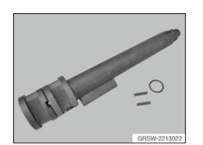
Holding sleeve AM
Replaced by: 83300493555
NOTE: (Centring sleeve set for piston rod/shock absorber) Spring tensioner 31 3 110/111 for tensioning coil springs/Replaced by 31 3 340 (0 493 555)
Consisting of:
1. Spring tensioner
NOTE: Replaced by 31 3 340 (0 493 555)
2. Holding sleeve
NOTE: (Centring sleeve) Replaced by 31 3 340 (0 493 555)
3. Holding sleeve
NOTE: (Centring sleeve) Internal thread M18x1.5 Replaced by 31 3 340 (0 493 555)
4. Holding sleeve
NOTE: (Centring sleeve) Internal thread M10x1 Replaced by 31 3 340 (0 493 555)
5. Holding sleeve
NOTE: (Centring sleeve) Internal thread M12x1.5 Replaced by 31 3 340 (0 493 555)
Holding sleeve Minimum set: Mechanical tools AM
NOTE: (Pressure sleeve) For removing and installing
Holding sleeve AM
NOTE: (Pressure sleeve) for removal discontinued, available as part of set of special tools only
Holding sleeve AM
NOTE: (pressure sleeve) For gripping the leading link. Series: E24, E28, E32, E34 Discontinued, only available via complete tool
Holding sleeve AM
NOTE: Sleeve H1 (removing gear finding component) in connection with adapter kit 1 (BMW), (81 64 2 155 745), for removal and installation of wheel bearings, propeller shafts and drive flanges.
SI number
08 06 09 (544)
Holding sleeve Minimum set: Mechanical tools AM
NOTE: (Pressure sleeve) for counterholding, discontinued, available as part of set of special tools only
Holding sleeve AM
Replaced by: 83300493555
NOTE: (Centring sleeve) Replaced by 31 3 340 (0 493 555)

Holding sleeve AM
NOTE: (Pressure sleeve) for installing discontinued, available as part of set of special tools only
Holding sleeve Minimum set: Mechanical tools AM
Replaced by: 83300493596
NOTE: (Pressure sleeve) For pulling out and in/model series: E38 Replaced by 31 2 263. (0 493 596)
Holding sleeve Minimum set: Mechanical tools AM
NOTE: (Pressure sleeve) For pulling out and in/model series: E30, E46. Can no longer be ordered separately. Only available as part of set 31 2 130 = 83 30 0 491 913.
Storage Location
B13
Holding sleeve AM
NOTE: Sleeve E1 (M24) in connection with adapter kit 1 (BMW), (81 64 2 155 745), for removal and installation of wheel bearings, propeller shafts and drive flanges.
SI number
08 06 09 (544)
Holding sleeve Mechanical tool
NOTE: For counter support when pressing the knurled bolts into the support bearing (spring strut)
Storage Location
B22
Holding sleeve AM
NOTE: (Pressure sleeve) For removing and installing the silent blocks in the wishbone.
Discontinued, can only be ordered using complete tool
Holding sleeve Minimum set: Mechanical tools AM
NOTE: (Push sleeve) For removing and installing Model series: E38, E39
Storage Location
B13
HYDRAULIC CYLINDERS
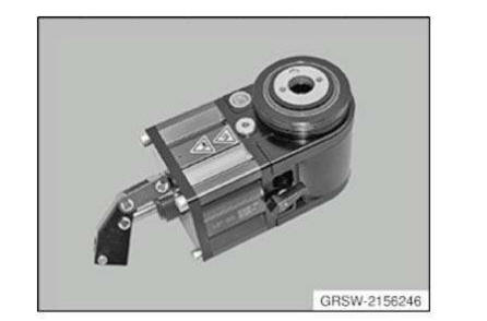
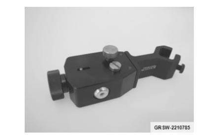
Hydraulic cylinders AM
NOTE: Hydraulic cylinder (hydraulic actuator) in connection with lever, (81 64 2 156 247), for removal and installation of wheel bearings, propeller shafts and drive flanges.
SI number
08 06 09 (544)
Insert
Insert Mechanical tool
NOTE: Protective insert As of 08/2011, replaces the previous special tool number 31 3 365
SI number
01 16 11 (738)
Insert Mechanical tool
NOTE: Protective insert As of 08/2011, replaces the previous special tool number 31 3 368
SI number
01 16 11 (738)
Insert AM
Replaced by: 83300493560
NOTE: (Protective insert) For spring retainer 31 3 122 Discontinuation and replaced by 31 3 350. (0 493 560)
Insert AM
Replaced by: 83300493560
NOTE: (Protective insert) For spring retainer 31 3 123 and 31 3 129 Discontinuation and replaced by 31 3 350. (0 493 560)
Insert AM
NOTE: (Protective insert) For spring retainer 31 3 325
Insert Mechanical tool
NOTE: Protective insert As of 08/2011, replaces the previous special tool number 31 3 364. Protective insert suitable for clamping plate 31 3 382 = 83 30 2 213 039.
SI number
01 16 11 (738)
Insert AM
In conjunction with: 31 3 352 = 83300493566
NOTE: Protective insert for clamping plate As of 08/2011, replaces the previous special tool number 31 3 362. Protective insert suitable for clamping plate 31 3 352 = 83 30 2 213 026.
SI number
01 16 11 (738)
Insert Mechanical tool
NOTE: Protective insert (blue) As of 08/2011, replaces the previous special tool number 31 3 369. Protective insert suitable for clamping plate 31 3 352 = 83 30 2 213 026.
SI number
01 16 11 (738)
Insert AM
NOTE: Protective insert As of 08/2011, replaces the previous special tool number 31 3 365. Protective insert suitable for clamping plate 31 3 355 = 83 30 2 213 034.
SI number
01 16 11 (738)
Insert Mechanical tool
NOTE: Protective insert (ring) As of 08/2011, replaces the previous special tool number 31 3 356. Protective insert suitable for clamping plate 31 3 354 = 83 30 2 213 031.
SI number
01 16 11 (738)
Insert AM
NOTE: (Protective insert) For spring retainer 31 3 322
Insert AM
NOTE: (Protective insert) For spring retainer 31 3 323
Insert AM
Replaced by: 83300493560
NOTE: (Protective insert) For spring retainer 31 3 125 Discontinuation and replaced by 31 3 350. (0 493 560)
Insert Mechanical tool
NOTE: Protective insert As of 08/2011, replaces the previous special tool number 31 3 363. Protective insert suitable for clamping plate 31 3 353 = 83 30 2 213 029.
SI number
01 16 11 (738)
Insert AM
NOTE: (Protective insert) For spring retainer 31 3 329
LASER
Laser Minimum set: Mechanical tools AM
LEVER
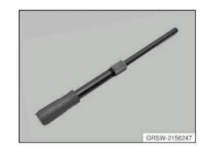
Lever AM
NOTE: Lever in connection with hydraulic cylinder (hydraulic actuator), (81 64 2 156 246), for removal and installation of wheel bearings, propeller shafts and drive flanges.
SI number
08 06 09 (544)
LOCATING FIXTURE
Locating fixture Minimum set: Mechanical tools AM
NOTE: For attaching and aligning the laser on the spring strut.
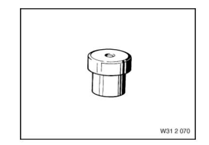
Mandrel
Mandrel Mechanical tool
NOTE: (drift) For output shaft radial sealing ring in the front axle differential
Mandrel Mechanical tool
NOTE: (Drift) For driving the radial shaft seals into the front wheel hubs and the input flange of the rear axle differential
Mandrel Mechanical tool
NOTE: (drift) For radial sealing ring of the drive shaft in the front axle differential
Measurement aid
Measurement aid Minimum set: Mechanical tools AM
NOTE: (Measuring aid) 2 units, to determine the vehicle ride height during wheel alignment --> > E36/7 (Z3)
Storage Location
C5
SI number
01 03 96 (042)
Consisting of:
1. Measurement aid
NOTE: (Measurement aid)
Measurement aid Minimum set: Mechanical tools AM
NOTE: Prism with mirror, for aligning the laser beam.
Measurement aid Minimum set: Mechanical tools AM
NOTE: (Measurement aid)
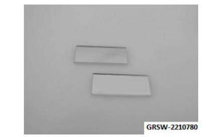
MIRRORS
Mirrors Minimum set: Mechanical tools AM
NOTE: 1 set (2 units) replacement for prism 83 30 2 210 780
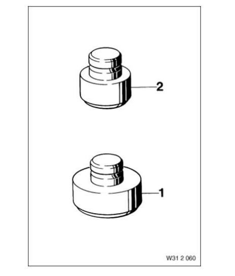
NUT
Nut AM
NOTE: (Nut with bearing) Can no longer be ordered separately. Only available as part of set 31 2 120 = 83 30 0 491 909.
Nut AM
NOTE: (Nut with bearing) Can no longer be ordered separately. Only available as part of set 31 2 120 = 83 30 0 491 909.
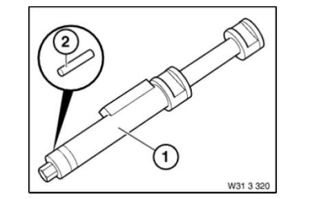
Pin
Pin AM
NOTE: (Replacement pins) Deletion, only available via tool set
Pin Minimum set: Mechanical tools AM
Replaced by: 83302213023
NOTE: Spare part set for basic device (2 locking pins and 1 O-ring) will be available under a new order number 83 30 2 213 023 as of July 2011
SI number
01 16 11 (738)
Pin Minimum set: Mechanical tools AM
NOTE: (Cylindrical pin)
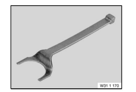
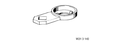
Pin wrench
Pin wrench AM
NOTE: For releasing and tightening down the spring strut bolt
Storage Location
Z1
Consisting of:
2 = Pin
NOTE: (Replacement pins) Deletion, only available via tool set
Pin wrench Mechanical tool
NOTE: For unfastening and tightening the spring-strut bolts when replacing the shock absorber
Pin wrench Mechanical tool
NOTE: For retightening the shock absorber screw connection in the spring strut without dismantling the spring strut
Storage Location
X10
Pin wrench Mechanical tool
NOTE: For releasing and tightening the spring-strut bolts when replacing the "Bilstein" gas-pressure shock absorber
Storage Location
X4
Pin wrench Mechanical tool
NOTE: For releasing and tightening the spring strut bolts when replacing the gas pressure shock absorbers
Storage Location
X4
Pin wrench Mechanical tool
NOTE: For unfastening and tightening the spring-strut bolts when replacing the shock absorber
Storage Location
X4
PIPE
Pipe AM
NOTE: (Guide tube) For installing
Pipe AM
NOTE: (Support tube) For installing the rubber mount in the front axle support - series: E12
PLATE
Plate AM
Replaced by: 83300492053
NOTE: Discontinuation and replaced by 33 4 200 (0 492 053)
Plate Minimum set: Mechanical tools AM
NOTE: Series: E30, E36, E46, E85
Storage Location
A7
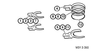
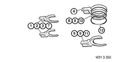
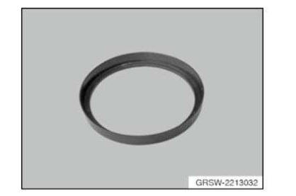
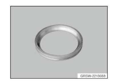
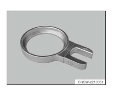
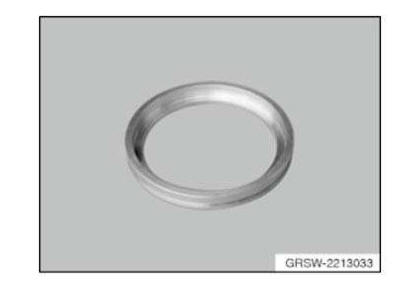
Ring
Ring AM
Replaced by: 83300493560
NOTE: (Spring retainer) With insert ring 31 3 101 only for series E46/without insert ring 31 3 101 for series E31, E39 front basic version Discontinuation and replaced by 31 3 350. (0 493 560)
Ring AM
Replaced by: 83302213038
NOTE: (Spring retainer ring) As of 08/2011, available under new item number 83 30 2 213 038.
SI number
01 16 11 (738)
Ring AM
Replaced by: 83302213032
NOTE: (Centering ring) As of 08/2011, available under new item number 83 30 2 213 032.
SI number
01 16 11 (738)
Ring AM
NOTE: (Centering ring) For centering the spring strut in the spring retainer ring 31 3 324 - Series: E46
Ring AM
NOTE: (Insert ring) For centring the spring strut in the spring retainer 31 3 124 - model series: E46
Ring AM
Replaced by: 83302213033
NOTE: (Insertion ring) As of 08/2011, available under new item number 83 30 2 213 033.
SI number
01 16 11 (738)
Ring AM
Replaced by: 83302213031
NOTE: (Spring retainer ring) As of 08/2011, available under new item number 83 30 2 213 031.
SI number
01 16 11 (738)
Ring Mechanical tool
NOTE: Aluminium spacer ring As of 08/2011, the previous special tool 31 3 358 receives this new item number.
SI number
01 16 11 (738)
NOTE: (Spring retainer ring) With centering ring 31 3 331 only for series E46/Without centering ring 31 3 331 for series E31, E39 front basis/model: Z3, Z3coupe
RING SPANNER
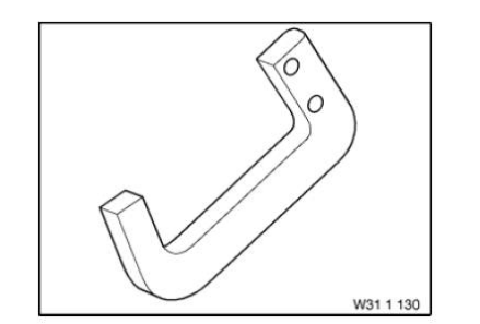
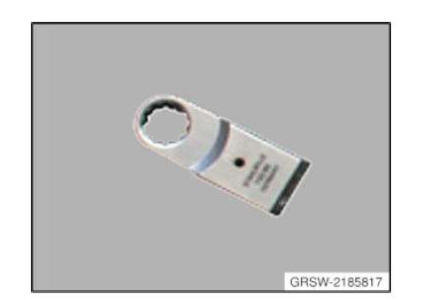
Ring spanner AM
NOTE: Ring fitting tool (ring spanner) to loosen and tighten the screw connections on wishbone and tension strut in conjunction with special tools set 81642185816 (extension).
SI number
08 04 10 (656)
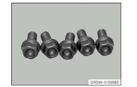
Screw
Screw Minimum set: Mechanical tools AM
NOTE: (Pressure bolt) Replaced by 31 2 311 (0 495 800)
Screw Mechanical tool
NOTE: (Hexagon screw M12x1.5x132 (4 units)) for screwing in the front axle support when removing and installing the front axle differential
Screw AM
NOTE: Screws K1 (M12x1.5) for removal and installation of wheel bearings, propeller shafts and drive flanges.
SI number
08 06 09 (544)
Screw AM
NOTE: Screws K2 (M14x1.5) for removal and installation of wheel bearings, propeller shafts and drive flanges.
SI number
08 06 09 (544)
Shaped part
Shaped part AM
NOTE: (shaped part) For trailing links without date stamp, up to model year 5/96
Shaped part Minimum set: Mechanical tools AM
NOTE: (Shaped part)
Shaped part Minimum set: Mechanical tools AM
NOTE: (Shaped part) Pressing off wishbone from wheel control joint E53, E83
Storage Location
C12
Shaped part Minimum set: Mechanical tools AM
NOTE: (Shaped part)
Shaped part Minimum set: Mechanical tools AM
NOTE: (Shaped part) Pressing off wishbone from wheel control joint E70. SI 1 01 07 (333)
Storage Location
B21
C21
SI number
01 01 07 (333)
Socket waf 46
Socket WAF 46 Minimum set: Mechanical tools Mechanical tool
NOTE: For expanding steering knuckle during spring strut removal
Storage Location
C47
SI number
01 05 03 (969)
SOCKET WRENCH
Socket wrench Mechanical tool
NOTE: (Socket wrench) for shock absorber support bearing
Storage Location
X3
SOCKET WRENCH INSERT
Socket wrench insert Minimum set: Mechanical tools Mechanical tool
NOTE: (Wrench socket 46 mm, 3/4" connection) For loosening and tightening wheel bearing unit
Storage Location
A10
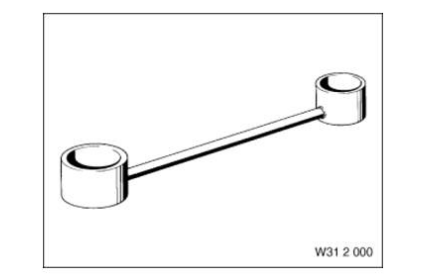
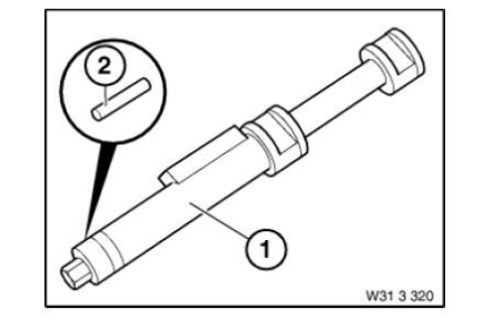
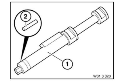
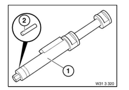
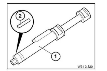
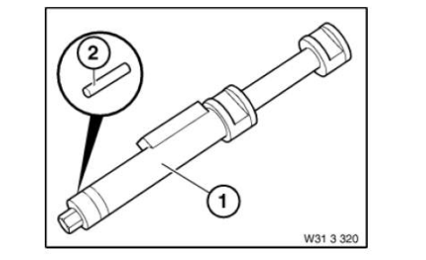
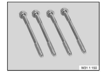
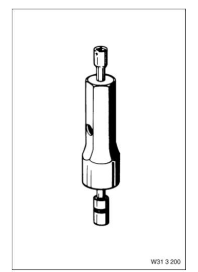
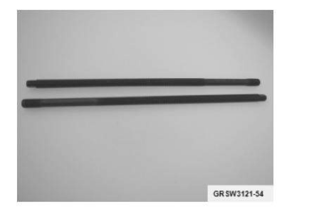
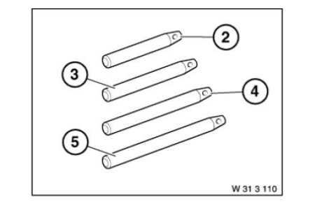
Spindle
Spindle Minimum set: Mechanical tools AM
Spindle AM
NOTE: Spindle F3 (M24/270mm) in connection with adapter kit 1 (BMW), (81 64 2 155 745) and MINI adapter kit (81 64 2 294 517) for removal and installation of wheel bearings, propeller shafts and drive flanges.
SI number
08 06 09 (544)
Spindle AM
NOTE: Spindle F2 (M20/M24/355mm) in connection with adapter kit 1 (BMW), (81 64 2 155 745), and MINI adapter kit, (81 64 2 294 517), for removal and installation of wheel bearings, propeller shafts and drive flanges.
SI number
08 06 09 (544)
Spindle AM
NOTE: With guide sleeve Discontinued, only available via complete tool
Spindle AM
Replaced by: 83300492053
NOTE: Discontinuation and replaced by 33 4 200 (0 492 053)
Spindle Minimum set: Mechanical tools AM
NOTE: Spindle (1 piece) series: E30, E36, E46, E85
Storage Location
A7
Spindle AM
Replaced by: 83300492053
NOTE: Replaced by 32 3 090. (0 492 053)
Spindle AM
NOTE: (Spindle M10 with fixture) discontinued, available as part of set of special tools only
Spindle AM
Spindle AM
NOTE: Spindle F1 (M24/425 mm) in connection with adapter kit 1 (BMW), (81 64 2 155 745), for removal and installation of wheel bearings, propeller shafts drive flanges.
SI number
08 06 09 (544)
Spindle AM
NOTE: With 2 nuts and 2 washers
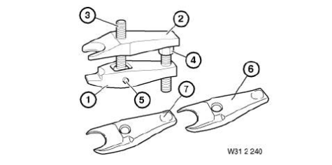
Spring tensioner
Spring tensioner Minimum set: Mechanical tools AM
Replaced by: 83302213022
NOTE: Basic device will receive a new order number as of July 2011
Storage Location
Individual
SI number
01 16 11 (738)
Consisting of:
1. Spring tensioner
NOTE: Basic device will be delivered under a new order number 83 30 2 213 022 beginning in July 2011.
2. Pin
NOTE: Spare part set for basic device (2 locking pins and 1 O-ring) will be available under a new order number 83 30 2 213 023 as of July 2011
Spring tensioner Mechanical tool
NOTE: Basic device incl. 2 locking pins and 1 O-ring, safety information and operating instructions. Corresponds to previous special tool number 31 3 340/31 3 341
SI number
01 16 11 (738)
Spring tensioner Minimum set: Mechanical tools AM
NOTE: Basic device will be delivered under a new order number 83 30 2 213 022 beginning in July 2011. Spare part (2 locking pins and 1 O-ring) is being delivered under a new order number 83 30 2 213 023
SI number
01 16 11 (738)
Spring tensioner AM
NOTE: (Spring tensioner without spring retainer)
Spring tensioner AM
Replaced by: 83300493555
NOTE: (Spring tensioner and spring retainer) For tensioning coil springs when removing and installing spring strut. Use only on the front axle. Exception: On E38 and E39 front and rear axle Replaced by 31 3 340. (0 493 555)
SI number
01 02 90 (168)
Consisting of:
1 = Spring tensioner
NOTE: (Spring tensioner without spring retainer) Discontinuation and replaced by 31 3 350. (0 493 560)
2 = Holder
NOTE: (Spring retainer (2 pieces)) With protective insert 31 3 127 - Model series: E32, E34 Touring, E36 Discontinuation and replaced by 31 3 350. (0 493 560)
3 = Holder
NOTE: (Spring retainer (2 pieces)) With protective insert 31 3 128 - Model series: E31, E38, E39 front high (2x) and basic version (1x) Discontinuation and replaced by 31 3 350. (0 493 560)
4 = Ring
NOTE: (Spring retainer) With insert ring 31 3 101 only for series E46/without insert ring 31 3 101 for series E31, E39 front basic version Discontinuation and replaced by 31 3 350. (0 493 560)
5 = Holder
NOTE: (Spring retainer (2 pieces)) With protective insert 31 3 126 - model series: E38 rear, E39 Saloon rear Discontinuation and replaced by 31 3 350. (0 493 560)
6 = Insert
NOTE: (Protective insert) For spring retainer 31 3 125 Discontinuation and replaced by 31 3 350. (0 493 560)
7 = Insert
NOTE: (Protective insert) For spring retainer 31 3 122 Discontinuation and replaced by 31 3 350. (0 493 560)
8 = Insert
NOTE: (Protective insert) For spring retainer 31 3 123 and 31 3 129 Discontinuation and replaced by 31 3 350. (0 493 560)
9 = Holder
NOTE: (Spring retainer) With protective insert 31 3 128 - model series: E46 Discontinuation and replaced by 31 3 350. (0 493 560)
11 = Ring
NOTE: (Insert ring) For centring the spring strut in the spring retainer 31 3 124 - model series: E46
Spring tensioner Minimum set: Mechanical tools Mechanical tool
NOTE: Complete set with newly defined delivery specification. As of 08/2011, replaces set 31 3 350 and 31 3 360.
SI number
01 16 11 (738)
Spring tensioner AM
NOTE: (Spring tensioner and spring retainer) For tensioning coil springs when removing and installing spring strut. Use only on the front axle. Exception: On E38 and E39 front and rear axle Replaced by 31 3 340 (0 493 555) 31 3 350 (0 493 560)
SI number
01 15 98 (344)
Consisting of:
1 = Spring tensioner
NOTE: (Spring tensioner without spring retainer)
2 = Holder
NOTE: (Spring retainer (2 pieces)) With protective insert 31 3 327 - Series: E32, E34, E36
3 = Holder
NOTE: (Spring retainer (2 pieces)) With protective insert 31 3 328 - Series: E31, E38, E39 front high (2x) and basis (1x)/model: Z3, Z3coupe
4 = Ring
NOTE: (Spring retainer ring) With centering ring 31 3 331 only for series E46/Without centering ring 31 3 331 for series E31, E39 front basis/model: Z3, Z3coupe
5 = Holder
NOTE: (Spring retainer (2 pieces)) With protective insert 31 3 326 - Series: E38 rear, E39 Saloon rear
6 = Insert
NOTE: (Protective insert) For spring retainer 31 3 325
7 = Insert
NOTE: (Protective insert) For spring retainer 31 3 322
8 = Insert
NOTE: (Protective insert) For spring retainer 31 3 323
9 = Holder
NOTE: (Spring retainer) With protective insert 31 3 332 - Series: E46
1 = Ring
NOTE: (Centering ring) For centering the spring strut in the spring retainer ring 31 3 324 - Series: E46
2 = Insert
NOTE: (Protective insert) For spring retainer 31 3 329
Spring tensioner AM
Replaced by: 83300493560
NOTE: (Spring tensioner without spring retainer) Discontinuation and replaced by 31 3 350. (0 493 560)
Replaced by: 83300493555
NOTE: Replaced by 31 3 340 (0 493 555)
SUPPORT
Support AM
NOTE: (Telescope supports) 4 pieces, no longer available separately, only via special tool set 31 5 250 (83 30 0 495 567)
SI number
01 24 06 (309)
Synchronising key
Synchronising key AM
NOTE: For wheel bearing race, outer
Synchronising key AM
NOTE: (Thrust piece) For removing
Synchronising key Mechanical tool
NOTE: For pressing the rubber mount out of the connecting pipe on the engine support
Storage Location
Y10
SI number
01 04 86 (566)
Synchronising key Minimum set: Mechanical tools AM
NOTE: Series: E30, E36, E46, E85
Storage Location
A7
Synchronising key Minimum set: Mechanical tools AM
NOTE: (Synchronizing key, diameter 79 mm) For mounting the rubber mount on the wishbone, series: E46
Storage Location
A7
Synchronising key Mechanical tool
NOTE: For pressing out the front wheel bearing
Storage Location
Y5
Synchronising key AM
Replaced by: 83300492053
NOTE: Discontinuation and replaced by 33 4 200 (0 492 053)

Synchronising key AM
NOTE: For removing and installing the rubber mount in the front axle support - series: E12

Synchronising key AM
NOTE: For installing
Synchronising key AM
NOTE: For removing
Synchronising key AM
NOTE: For wheel bearing race, inner
Synchronising key Mechanical tool
NOTE: For pressing the roller bearing onto the differential housing
Tool
Tool Mechanical tool
NOTE: Clamping plate As of 08/2011, the previous special tool 31 3 353 receives this new item number
SI number
01 16 11 (738)
Tool Minimum set: Mechanical tools AM
NOTE: For removing and installing silent blocks in wishbone support brackets
Storage Location
B13
Consisting of:
1. Holding sleeve
NOTE: (Pressure sleeve) For pulling out and in/model series: E30, E46. Can no longer be ordered separately. Only available as part of set 31 2 130 = 83 30 0 491 913.
2. Holding sleeve
NOTE: (Pressure sleeve) For counter-holding/model series: E30 Replaced by 31 2 133. (0 491 916)
3. Holding sleeve
NOTE: (Pressure sleeve) For pulling out and in/model series: E30 All-wheel drive vehicle, E34, E36, E46 Can no longer be ordered separately. Only available as part of set 31 2 130 = 83 30 0 491 913.
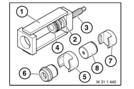
Tool AM
NOTE: For removing and installing the silent blocks in the wishbones and leading links.
Storage Location
A13
Consisting of:
5 = Holding sleeve
NOTE: (Pressure sleeve) For gripping the wishbones and for removing and installing the silence blocks in the leading link. Discontinued, can only be ordered using complete tool
1 = Holding sleeve
NOTE: (Pressure sleeve) For removing and installing the silent blocks in the wishbone. Discontinued, can only be ordered using complete tool
2 = Holding sleeve
NOTE: (Pressure sleeve) For gripping the wishbones and for removing and installing the silence blocks in the leading link. Replaced by 31 1 054. (0 493 747)
3 = Holding sleeve
NOTE: (pressure sleeve) For gripping the leading link. Series: E24, E28, E32, E34 Discontinued, only available via complete tool
Tool Minimum set: Mechanical tools AM
NOTE: (Pressure bush tool) For removing and installing rubber mounts in trailing and leading links and in wishbones (E46/5)
Storage Location
B13
SI number
01 03 99 (418)
Consisting of:
4 = Holding sleeve
NOTE: (Push sleeve) For removing and installing. Series: E53, E83
1 = Holding sleeve
NOTE: (Push sleeve) As counter support when removing and installing. Series: E38, E39, E83 For removing and installing rubber mounts in wishbones/Model series: E46/5
2 = Holding sleeve
NOTE: (Pressure sleeve) For pulling out and in/model series: E38 Replaced by 31 2 263. (0 493 596)
3 = Holding sleeve
NOTE: (Push sleeve) For removing and installing Model series: E38, E39
Tool Mechanical tool
NOTE: The spare parts set (2 locking pins and 1 O-ring) for reorders corresponds to the previous special tool 31 3 342
SI number
01 16 11 (738)
Tool AM
NOTE: For pressing in the wheel bearing race - model year: up to 82
Consisting of:
1. Synchronising key
NOTE: For wheel bearing race, inner
2. Synchronising key
NOTE: For wheel bearing race, outer
Tool Minimum set: Mechanical tools AM
NOTE: (Extractor) For pressing off wishbone from steering stub.
Storage Location
C12
SI number
01 06 94 (801)
Consisting of:
6 = Shaped part
NOTE: (Shaped part) Pressing off wishbone from wheel control joint E53, E83
7 = Shaped part
NOTE: (Shaped part) Pressing off wishbone from wheel control joint E70. SI 1 01 07 (333)
1 = Shaped part
NOTE: (Shaped part)
2 = Shaped part
NOTE: (Shaped part)
3 = Spindle
4 = Screw
NOTE: (Pressure bolt) Replaced by 31 2 311 (0 495 800)
5 = Pin
NOTE: (Cylindrical pin)
Tool Mechanical tool
NOTE: Clamping plate As of 08/2011, the previous special tool 31 3 355 receives this new item number
SI number
01 16 11 (738)
Tool AM
NOTE: For removing and installing the silent blocks in the tension struts and wishbones.
Storage Location
Y10
Consisting of:
1. Holding sleeve
NOTE: (Pressure sleeve) for removal discontinued, available as part of set of special tools only
2. Holding sleeve
NOTE: (Pressure sleeve) for counterholding, discontinued, available as part of set of special tools only
3. Holding sleeve
NOTE: (Pressure sleeve) for installing discontinued, available as part of set of special tools only
Tool set
Tool set Mechanical tool
NOTE: Retrofit - for authorised BMW dealers who have already received the special tool 31 0 000 from SPX
SI number
01 19 10 (674)
Tool set AM
NOTE: Threaded spindle set for removing and installing the rubber mount on the rear axle support.
SI number
08 06 10 (658)
Consisting of:
4 = 2208574
3 = 2208575
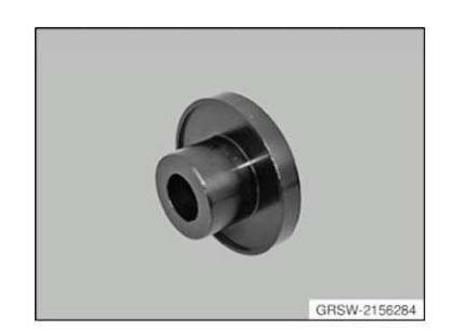
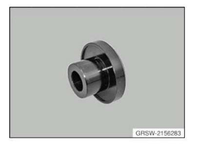
Tool set AM
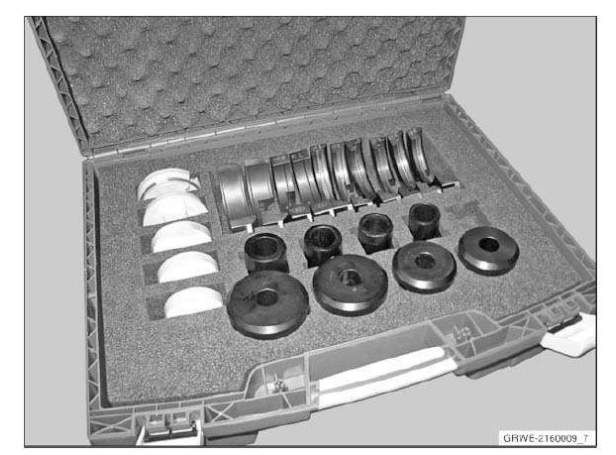
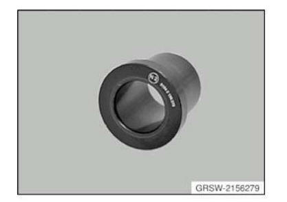
NOTE: Adapter kit 2 (BMW), (BMW-specific adapters), for installation and removal of wheel bearings, propeller shafts and drive shafts.
SI number
08 12 14 (155)
Consisting of:
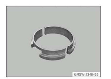
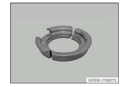
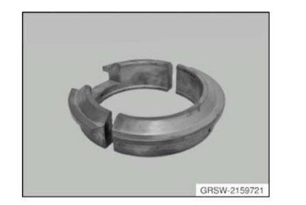
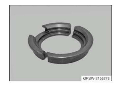
1 = 2159721
14 = 2159722
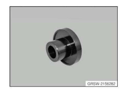
18 = 2156282
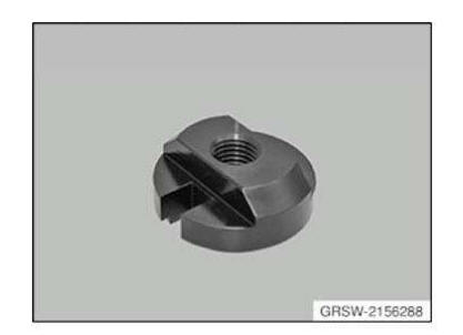
| 17 = 2156283
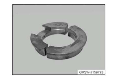
2 = 2159723
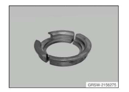
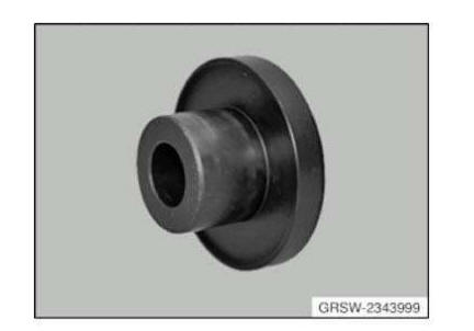
16 = 2156275
15 = 2156273
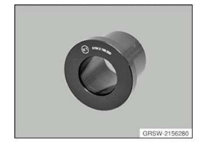
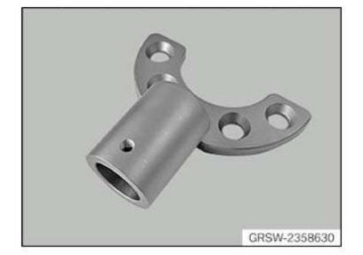
13 = 2156280
12 = 2156279
11 = 2156278
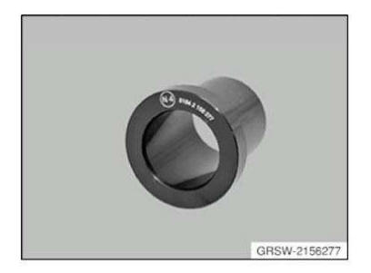
10 = 2156277
Tool set AM
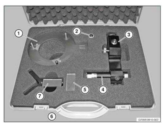
NOTE: A set of the BMW hydraulic tool system for wheel bearings and output shafts (basic set for BMW, consisting of 81 64 2 155 744, 81 64 2 155 745, 81 64 2 155 746)
SI number
08 12 14 (155)
Tool set AM
NOTE: Hydraulic unit (basic unit) for removal and installation of wheel bearings, propeller shafts and drive flanges.
SI number
08 12 14 (155)
Consisting of:
2 = 2156247
1 = 2156246
Tool set Minimum set: Mechanical tools AM
In conjunction with: 2357190
NOTE: For positioning the support bearing on the spring strut of the front axle Fitting aid that replaces (blocked) tool 31 0 000
SI number
01 19 10 (674)
Consisting of:
1 = Gauge
NOTE: For positioning the support bearing.
2 = Battery
NOTE: commercially available battery 3V lithium (CR 123A)
3 = Locating fixture
NOTE: For attaching and aligning the laser on the spring strut.
4 = Laser
5 = Mirrors
NOTE: 1 set (2 units) replacement for prism 83 30 2 210 780
7 = Measurement aid
NOTE: Prism with mirror, for aligning the laser beam.
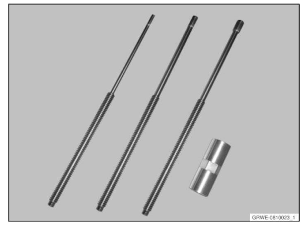
Tool set AM
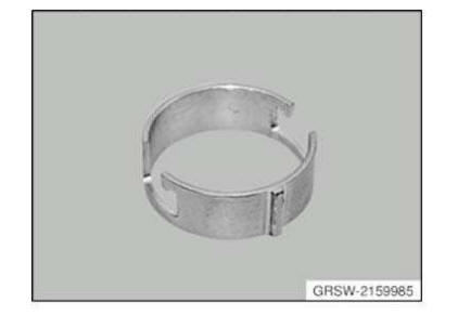
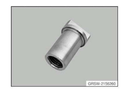
NOTE: Wheel bearing adapter kit 1 (BMW), (spindles and tensioning nuts) for removal and installation of wheel bearings, propeller shafts and drive flanges.
SI number
08 12 14 (155)
Consisting of:
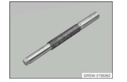
15 = 2156262
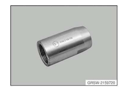
14 = 2159720
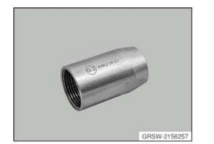
13 = 2156257
12 = 2156256
11 = 2318476
10 = 2159986
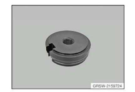
9 = 2159985
1 = 2156252
2 = 2156253
3 = 2156254
4 = 2156255
5 = 2156258
6 = 2156260
7 = 2156265
8 = 2156271
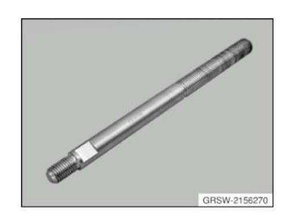
16 = 2156270
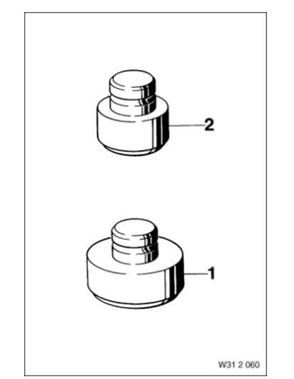
Washer
Washer AM
NOTE: (Flanged washer) For centring of threaded spindle and as a support disc for removing and installing the rubber mount in the front axle support and in the wishbones - series: E12
Washer AM
NOTE: Contact disc D1 in connection with adapter kit 1 (BMW), (81 64 2 155 745) and MINI adapter kit (81 64 2 294 517), for removal and installation of wheel bearings, propeller shafts and drive flanges.
SI number
08 06 09 (544)
Washer AM
NOTE: (Measuring disc 7 mm)
Washer AM
NOTE: Contact disc (M24) E3 in connection with adapter kit 1 (BMW), (81 64 2 155 745) and MINI adapter kit (81 64 2 294 517), for removal and installation of wheel bearings, propeller shafts and drive flanges.
SI number
08 06 09 (544)
Washer Mechanical tool
NOTE: (Spring washer) For pretensioning the differential side gears when determining the installation size in the front axle differential
Washer Mechanical tool
NOTE: For installing the outer bearing race in the bearing housing in the front axle differential
Washer Mechanical tool
NOTE: For determining the installation play of the radial gears in the front axle differential
WRENCH
Wrench Minimum set: Mechanical tools Mechanical tool
NOTE: For releasing and tightening the shock absorber support bearing bolt
Storage Location
A11
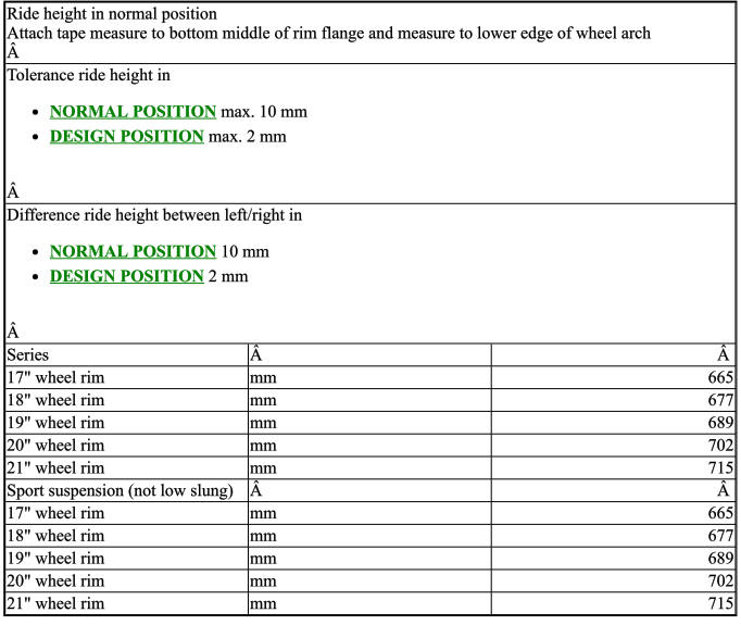
FRONT AXLE - RIDE HEIGHT
FRONT AXLE - RIDE HEIGHT SPECIFICATION
FRONT AXLE DIFFERENTIAL, 170AL/175AL
FRONT AXLE DIFFERENTIAL SPECIFICATION

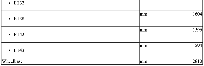
GENERAL - TRACK WIDTH/WHEELBASE
GENERAL - TRACK WIDTH/WHEELBASE SPECIFICATION

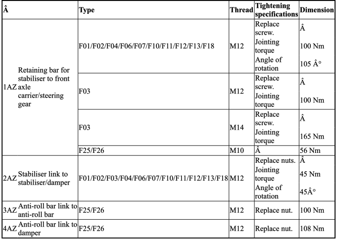
ANTI-ROLL BAR
TIGHTENING TORQUE SPECIFICATION - ANTI-ROLL BAR
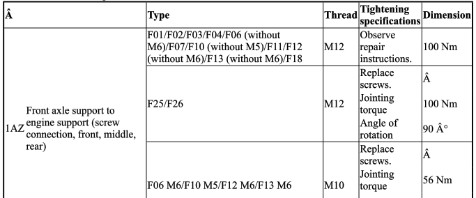
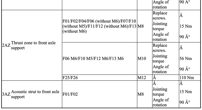
FRONT AXLE SUSPENSION
TIGHTENING TORQUE SPECIFICATION - FRONT AXLE SUSPENSION
FRONT AXLE DIFFERENTIAL
TIGHTENING TORQUE SPECIFICATION - FRONT AXLE DIFFERENTIAL
OUTPUT SHAFT
TIGHTENING TORQUE SPECIFICATION - OUTPUT SHAFT

SPRING STRUTS
TIGHTENING TORQUE SPECIFICATION - SPRING STRUTS
TRAILING ARMS AND STRUTS
TIGHTENING TORQUE SPECIFICATION - TRAILING ARMS AND STRUTS
WHEEL BEARINGS AND STEERING KNUCKLE
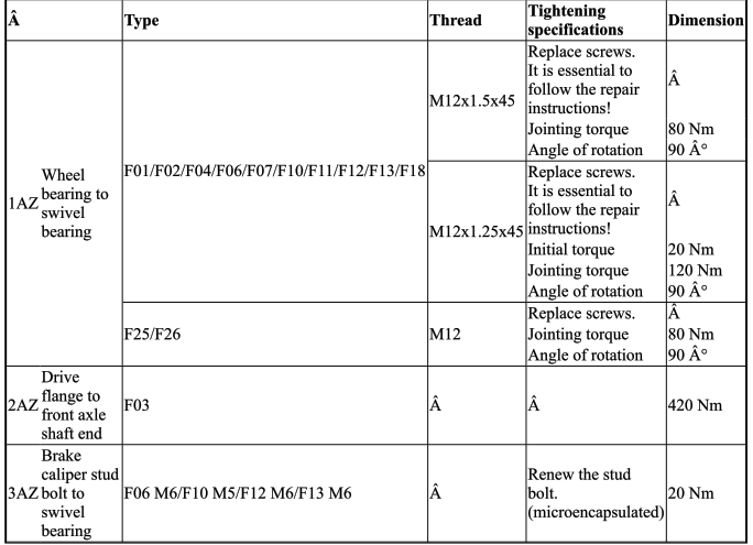
TIGHTENING TORQUE SPECIFICATION - WHEEL BEARINGS AND STEERING KNUCKLE
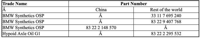
TRANSMISSION OIL FOR FRONT AXLE DIFFERENTIAL
FRONT AXLE FINAL DRIVE OILS CHART
GREASE FOR WHEEL BEARING
WHEEL BEARING GREASE CHART
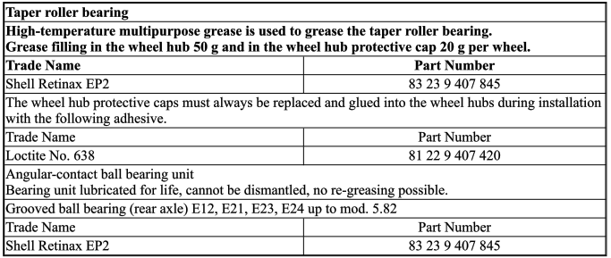

 General information on high temperature multi-purpose grease
1.0 GENERAL INFORMATION ON HIGH TEMPERATURE MULTI-PURPOSE
GREASE
High temperature multi-purpose grease consists of a lithium complex soap in a min ...
Other materials:
BMW X3 (F25) Service & Repair Manual > Suspension: Final drive oil for bmw m1 motorsport coupe
3.0 FINAL DRIVE OIL FOR BMW M1 MOTORSPORT COUPE
The final drive of a BMW M1 is integrated into the manual transmission and the oil supply is accomplished
with a mutual oil filling.
Use reputable brand SAE 80 manual transmission oil conforming with specifications MIL-L-2105 A or API-
GL 4.
4 ...
