BMW X3 (F25) Service & Repair Manual: Steering gear with servo unit
- Notes on replacement of steering gear/steering column/steering shaft following accident damage
- Replace electrical steering box (eps) (N52/N55/N57)
- Replace electrical steering gear (eps) (N20/N47)
- Replace electrical steering gear (eps) (N20/N47)
Notes on replacement of steering gear/steering column/steering shaft following accident damage
Steering gear facts: In the event of accidents or driving conditions similar to accidents, shock-like loads can cause different types of damage to steering boxes. When a steering box is externally undamaged, it is sometimes only possible to identify damage with great difficulty and with great effort. However, damage of this nature poses an unacceptable risk to the vehicle because it can result in failure of the steering system.
Due to the disproportionate amount of effort involved, it is generally not sensible to check thoroughly all the individual components of the steering box and as an alternative it is necessary to take into account other components which can be checked more easily.
Steering gear procedure:
The steering box must be replaced if one or more of the following points apply:
A. Visible or noticeable damage to the steering box
- Version with electric steering box (EPS): Examine in particular the control unit with all plug connections for damage and hairline cracks.
B. Unacceptable torque increase and jamming when the steering box is turned from lock to lock (without hydraulic/electrical assistance).
C. Permissible tolerances exceeded during axle/wheel alignment (include alignment record with invoice/report if necessary).
D. Fire damage
E. Damage, permanent deformation or fractures to:
- Wheel rims in the event of a negative result from the wheel alignment check
- Spring struts, steering stubs, wheel carriers
- Wishbones
- Struts or trailing links or anti-roll bar with this function
- Body-side screwing/attachment points for wheel guide/control components
- Front axle support
- Pitman arms
- Track rods
- Steering box fixtures
- Steering Column
NOTE: If the steering box replacement work which is required for safety reasons is refused by the customer or an insurance company for cost reasons, a memorandum to that effect must be drawn up and countersigned by the party bearing the costs of the accident repair.
Facts on steering column and steering shaft: In the event of accidents or driving conditions similar to accidents, shock-like loads can cause different types of damage to the steering shafts and to the steering columns. In case no external damaged of the steering column and the steering shaft can be noticed, it is sometimes only possible to identify damage with great difficulty and with great effort.
Procedure for steering column and steering shaft:
The steering column and the steering shaft need to replaced if one or more of the following points apply:
- Visible or noticeable damage, deformation or breakage of the steering column or the steering shaft
- Damage, permanent deformation or breakage of the track rod
- Unacceptable torque increase and jamming when the steering column is turned from limit position to limit position (without hydraulic/electrical support)
- Permissible tolerances exceeded after wheel alignment (include alignment record with invoice/report if necessary)
- Positive check for activated crash system of the mechanical steering column: If there is no visible damage to the steering column, the steering column needs to be checked for an activated crash system:
- Open steering column lock
- Pull steering wheel out towards the driver (towards the body) until the physical limit position is reached, but do not use excessive force
-
Push steering wheel towards engine compartment (approx. 20-30 mm away from body) into the
comfort position and lock.
If no end stop is present when pulling out the steering column or if the gaiter of the steering column shroud is tensioned, the crash system was activated and the steering column needs to be renewed.
NOTE: If the replacement of the steering column/steering shaft work which is required for safety reasons is refused by the customer or an insurance company for cost reasons, a memorandum to that effect must be drawn up and countersigned by the party bearing the costs of the accident repair.
IMPORTANT: The vehicle's operating licence will be invalidated whenever the function of any of its safety components is compromised!
This guideline is binding for all accident repairs to BMW and MINI vehicles!
Replace electrical steering box (eps) (N52/N55/N57)
IMPORTANT: Connecting line: In the event of moisture/corrosion inside the two plug connections, check the insulation of the connecting line. If the insulation reveals any noticeable/striking features, partial replacement will be necessary. Otherwise it will be sufficient to replace the contacts or connector housing.
NOTE: In a warranty case you must always provide a fault memory printout, even where there is no fault entry, with the defective part.
IMPORTANT: Do not turn the steering wheel once the steering shaft has been detached from the steering gear.
If the lower section of the steering shaft is separated from the steering gear, the steering column switch cluster may be damaged when the steering wheel is turned.
Necessary preliminary tasks:
- Disconnect BATTERY EARTH LEAD .
NOTE: High-current-carrying wiring laid with permanent positive connection (80 A fuse).
- Remove UNDERBODY PROTECTION .
- Release BOTTOM OF STEERING SHAFT AT STEERING BOX.
- Release LEFT AND RIGHT TRACK ROD END at swivel bearing.
- Lower FRONT AXLE SUPPORT .
- Loosen ANTI-ROLL BAR on the front left and right.
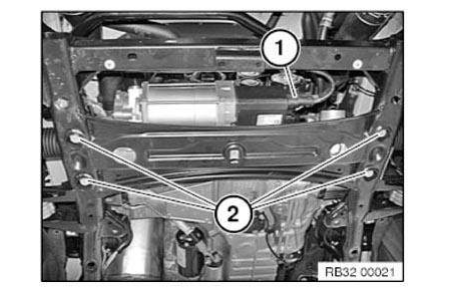
Unlock plug connections (1) and disconnect.
Unfasten screws (2).

IMPORTANT: Risk of damage! Pay attention to connector housing on steering box while removing steering box! Carefully remove steering gear towards the front!
Installation note: Remount TRACK ROD END on left and right.
After installation:
- Turn steering wheel in both directions to the limit position. The airbag indicator light must not light up in the process.
- Carry out PROGRAMMING/ENCODING .
- Teach in END STOP SOFTWARE.
- Perform CHASSIS/WHEEL ALIGNMENT CHECK.
Replace electrical steering gear (eps) (N20/N47)
IMPORTANT: Connecting line: In the event of moisture/corrosion inside the two plug connections, check the insulation of the connecting line. If the insulation reveals any noticeable/striking features, partial replacement will be necessary. Otherwise it will be sufficient to replace the contacts or connector housing.
NOTE: In a warranty case you must always provide a fault memory printout, even where there is no fault entry, with the defective part.
IMPORTANT: Do not turn the steering wheel once the steering shaft has been detached from the steering gear.
If the lower section of the steering shaft is separated from the steering gear, the steering column switch cluster may be damaged when the steering wheel is turned.
Necessary preliminary tasks:
- Disconnect BATTERY EARTH LEAD .
NOTE: High-current-carrying wiring laid with permanent positive connection (80 A fuse).
- Remove UNDERBODY PROTECTION .
- Remove FRONT WHEEL on the left and right.
- Release LEFT WISHBONE at front axle carrier.
- Release LEFT TENSION STRUT at front axle carrier.
- Release LEFT AND RIGHT TRACK ROD END at swivel bearing.
- Release ANTI-ROLL BAR LINK at antiroll bar, left and right.
- Release ANTI-ROLL BAR at front axle carrier, left and right.
- Release BOTTOM OF STEERING SHAFT AT STEERING BOX.
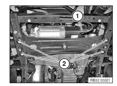
Unlock plug connections (1) and disconnect.
Unfasten screws (2).

IMPORTANT: Risk of damage! Pay attention to connector housing on steering box while removing steering box! Press back spring strut a little.
Hold up anti-roll bar.
Carefully remove steering box towards left-hand side.
Installation note: Remount TRACK ROD END on left and right.
After installation:
- Turn steering wheel in both directions to the limit position. The airbag indicator light must not light up in the process.
- Carry out PROGRAMMING/ENCODING .
- Teach in END STOP SOFTWARE.
- Perform CHASSIS/WHEEL ALIGNMENT CHECK.
Replace electrical steering gear (eps) (N20/N47)
IMPORTANT: Connecting line: In the event of moisture/corrosion inside the two plug connections, check the insulation of the connecting line. If the insulation reveals any noticeable/striking features, partial replacement will be necessary. Otherwise it will be sufficient to replace the contacts or connector housing.
NOTE: In a warranty case you must always provide a fault memory printout, even where there is no fault entry, with the defective part.
IMPORTANT: Do not turn the steering wheel once the steering shaft has been detached from the steering gear.
If the lower section of the steering shaft is separated from the steering gear, the steering column switch cluster may be damaged when the steering wheel is turned.
Necessary preliminary tasks:
- Disconnect BATTERY EARTH LEAD .
NOTE: High-current-carrying wiring laid with permanent positive connection (80 A fuse).
- Remove UNDERBODY PROTECTION .
- Release LEFT WISHBONE at front axle carrier.
- Release LEFT TENSION STRUT at front axle carrier.
- Release LEFT AND RIGHT TRACK ROD END at swivel bearing.
- REMOVE left output shaft.
- Release ANTI-ROLL BAR at front axle carrier, left and right.
- Release ANTI-ROLL BAR LINKS at anti-roll bar, left and right.
- Release BOTTOM OF STEERING SHAFT AT STEERING BOX.
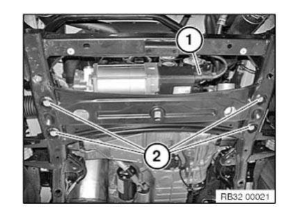
Unlock plug connections (1) and disconnect.
Unfasten screws (2).

IMPORTANT: Risk of damage! Pay attention to connector housing on steering box while removing steering box! Press back spring strut a little.
Hold up anti-roll bar.
Carefully remove steering box towards left-hand side.
Installation note: Remount TRACK ROD END on left and right.
After installation:
- Turn steering wheel in both directions to the limit position. The airbag indicator light must not light up in the process.
- Carry out PROGRAMMING/ENCODING .
- Teach in END STOP SOFTWARE.
- Perform CHASSIS/WHEEL ALIGNMENT CHECK.
TEACHING IN END STOP SOFTWARE FOR ELECTRIC STEERING GEAR (EPS)
NOTE: The end stop software must be taught in:
- after the steering gear is replaced
- after programming/coding
Connect vehicle to BMW diagnosis system.
Select and perform end stop under Service functions.
Other materials:
BMW X3 (F25) Owners Manual > Notes: Reporting safety defects
For US customers
The following only applies to vehicles owned
and operated in the US.
If you believe that your vehicle has a defect
which could cause a crash or could cause injury
or death, you should immediately inform
the National Highway Traffic Safety Administration
NHTSA, in addition t ...


