BMW X3 (F25) Service & Repair Manual: Wheels
- Checking one road wheel on balancing machine for lateral and radial runout (wheel removed)
- Checking wheel rim for lateral and radial runout
- Notes for repairing aluminum rims
- Remove or install front or rear wheel
- Stationary wheel balancing
Checking one road wheel on balancing machine for lateral and radial runout (wheel removed)
Special tools required:
- 36 1 030
- 36 1 031
- 36 1 032
- 36 1 033
- 36 1 034
- 36 1 035
- 36 1 036
Necessary preliminary tasks:
- Remove WHEEL
Mount wheel in balancing machine.
To avoid clamping errors, fit the wheel on the balancing machine in the same way as it is also fitted on the vehicle (valve position facing down).
Use suitable wheel centering element supplied with corresponding balancing machine.
- Basic flange.
- Wheel centering element.
- Type flange.
- Clamping nut.
Use special tool 36 1 030 for checking.
Special tool 36 1 030 consists of:
- Base 36 1 031
- Post with clamp 36 1 032
- Holder with clamp 36 1 033
- Clamp 36 1 034
- Measuring roll 36 1 035
- Dial gauge 36 1 036
Position special tool 36 1 030 on tire tread surface.
Turn wheel by hand and measure max. radial tire runout .
NOTE: Measuring device must be vertical to tire tread surface.
Position special tool 36 1 030 on tire sidewall.
Turn wheel by hand and measure max. lateral tire runout .
NOTE: Measuring device must be vertical to tire side wall.
Never measure on tire inscription! If necessary, check DISC WHEEL (wheel rim) for radial and face runout.
Checking wheel rim for lateral and radial runout
Necessary preliminary tasks:
- Remove WHEEL.
- Check WHEEL for lateral and radial runout.
- Remove Tire from disc wheel.
- Remove dirt from rim base and rim flange.
IMPORTANT: Disc wheels are not allowed to be repaired!
Mount disc wheel in balancing machine.
Use suitable wheel centering element supplied with corresponding balancing machine.
- Basic flange
- Wheel centering element
- Type flange
- Clamping nut
Place dial gauge sensor on rim shoulder.
Turn wheel by hand and measure max. radial runout .
Carry out measurement on both rim shoulder sides.
NOTE: Dial gauge must be vertical to rim shoulder.
Position sensor on rim flange.
Turn wheel by hand and measure max. lateral runout . Carry out measurement on both rim flanges.
NOTE: Dial gauge must be vertical to rim flange.
IMPORTANT: Avoid clamping errors during subsequent installation work.
Notes for repairing aluminum rims
In general, the economic viability must be checked prior to the repair.
It is possible to repair the following damage (applies to cast aluminum rims labelled as AlSi7 AlSi11, AlSi12):
- Depth of the damage in the aluminum at maximum 1 mm
- Distance of the damage from the outer rim edge at maximum 50 mm
- Paintwork damage on the remaining wheel rim
It is not possible to repair the following damage:
- Deformation and cracks
- Polished, forged aluminum wheel rims are unsuitable for repair.
NOTES ON EXCHANGING TIRES DURING REPAIR
General:
- The tire size, manufacturer and tire tread must be the same on one axle
- To meet the BMW standards, the vehicle should be equipped with tires from the same manufacturer and with the same tire tread (tires approved by BMW) on all 4 wheels
- The difference in tire tread depth on one axle must not exceed 2 mm (control quality of suspension control systems and wheel alignment requirement)
- The tires with the higher tread depths must be mounted on the rear axle
- The DOT age difference must not exceed 4 years
- On exchanging the tires, the tire pressure must be adjusted
Additionally for all-wheel drive vehicles:
- The tire size, manufacturer and tire tread must be identical on all wheels; if mixed tires are fitted, different dimensions are permissible.
- The difference in tire tread depth on all wheels must not exceed 2 mm (control quality of suspension control systems and wheel alignment requirement)
Remove or install front or rear wheel
Special tools required:
- 36 1 300
- 81 25 2 344 011
- 36 1 335
- 36 1 010
IMPORTANT: Wheel was balanced electronically.
Observe safety information on raising the vehicle.
Adhere to the instructions on initializing the Run Flat Indicator (RPA).
During the installation of all four wheels (e.g. when changing from summer to winter wheels), the tire pressure must be checked! Observe the notes on tolerance compensation for the tire pressure control!
Observe the following procedure to prevent clamping errors and imbalance:
- Loosen wheel studs.
- Wheel positioned with valve facing down.
- If several wheels are simultaneously removed, mark installation position of wheels on tires (e.g. with a piece of chalk).
- Mark out wheel to wheel hub.
- Mark out lockable wheel stud in relation to wheel.
- Unscrew wheel studs. Remove wheel.
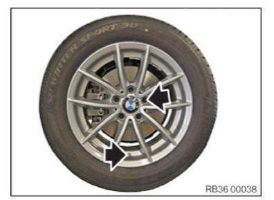
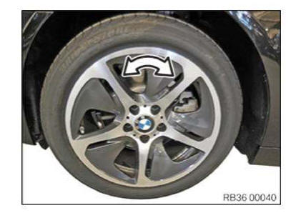
IMPORTANT: Some of the rim styling must be positioned in a certain direction! Observe direction-of-rotation arrow on the wheel rim.
IMPORTANT: Contact surfaces between:
- brake disc and wheel rim,
- brake disc and wheel hub,
must be clean and free from grease.
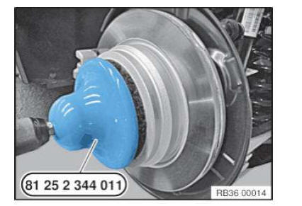
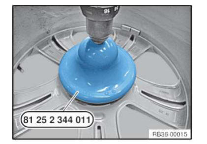
Remove dirt, grease residues and corrosion from contact surface with a drill and special tool 81 25 2 344 011.
IMPORTANT: Do not operate special tool 81 25 2 344 011 with an impact screwdriver!
NOTE: Degrease contact surface with universal cleaner.
NOTE: If there are grease residues in the area of the wheel stud hole, the brake disc must be removed and cleaned.
Remove dirt, grease residues and corrosion from contact surface with a drill and special tool 81 25 2 344 011.
IMPORTANT: Do not operate special tool 81 25 2 344 011 with an impact screwdriver!
NOTE: Degrease contact surface with universal cleaner.
Check brake disc retaining bolt (1) for tight fit.
IMPORTANT: Mounting bolt (1) must not under any circumstances protrude over contact surface (2) between brake disc and wheel rim.
Tightening torque brake disc retaining bolt:
- Front axle 34 11 1AZ
- Rear axle 34 21 1AZ
Apply a thin coat of grease to wheel centering (1) in wheel rim.
NOTE: To release and tighten lockable wheel bolts, use a matching adapter from special tool 36 1 300, 36 1 335 or 36 1 010.
Clean wheel studs and check threads for damage, replace, if necessary.
Replace rusty wheel studs.
IMPORTANT: Do not apply oil to wheel studs.
IMPORTANT: Under no circumstances use pneumatic or electric screwdrivers to install and tighten the wheel studs.
IMPORTANT: Wheel rim must rest uniformly against the brake disc.
In the case of non-original BMW wheel studs/rims it may be necessary to retighten the wheel studs on account of setting properties (refer to manufacturer's documents).
Tightening specifications:
1. Screw in wheel bolts and evenly tighten crosswise by hand in order to center the wheel rim.
2. Tighten down wheel studs in crosswise sequence with a calibrated torque wrench to prescribed tightening torque 36 10 1AZ .
3. Check all the wheel bolts in the same order or retighten to the prescribed tightening torque again.
Stationary wheel balancing
Special tools required:
- 36 1 010
- 36 1 020
Necessary preliminary tasks:
- Remove WHEEL.
IMPORTANT: Use only BMW-approved balance weights.
Remove any fitted balancing weights, stones in tread pattern and larger dirt contaminations.
Check tire pressure and tire for condition, damage, flat spots (irregularities caused by e.g. parking of vehicle with tires which have run hot). If necessary, check WHEEL AND TIRE for radial and lateral runout.
Use BMW-approved wheel centering elements of relevant balancing machine manufacturers.
- Basic flange
- Wheel centering element
- Type flange
- Clamping nut
IMPORTANT: To avoid clamping errors, it will be necessary to fit the wheel on the balancing machine in the same way (e.g. valve facing down) as it is then fitted on the vehicle.
Balance wheel in accordance with operating instructions of relevant balancing machine.
On light-alloy rims with distinctive J-shape rim flange, proceed as follows:
- Gently force off tire sidewall with special tool 36 1 020 at appropriate point from rim flange.
- Install retaining clip (1).
- Remove special tool 36 1 020 .
Raise retaining clip with special tool 36 1 010. Slide balance weight underneath and allow it to snap into place.
Arrangement of balance weights for light-alloy rims with distinctive J-shape rim flanges.
- Retaining spring
- Balance weight
Adhesive weights must be used on all other light-alloy rims.
Max. imbalance.
NOTE: When using adhesive weights, proceed as follows:
- Carefully remove any adhesive weights. Do not damage wheel rim when doing so.
- Select suitable location for fitting.
- Clean adhesive area thoroughly.


Other materials:
BMW X3 (F25) Service & Repair Manual > Transmission: Transmission case, oil sump
REMOVING AND INSTALLING/SEALING OR REPLACING TRANSMISSION OIL SUMP
(GA8HP45Z)
IMPORTANT:
Do not let skin come in contact with transmission oil and do not inhale fuel vapors.
Wear protective gloves.
Ensure adequate ventilation.
IMPORTANT:
Remove transmiss ...
