BMW X3 (F25) Service & Repair Manual: Side panels
- Removing and installing front side panel on left
- Replacing left rear side panel
- Stripping operations - replacing rear side panel, left
Removing and installing front side panel on left
Observe GAP DIMENSIONS.
IMPORTANT: Do not damage adjoining body components.
Necessary preliminary tasks:
- Remove TRIM COVER FROM WHEEL ARCH at front left
- Remove WATER COLLECTION STRIP ON WINDSCREEN
- F25 only: Remove SIDE REPEATER
- Partially detach FRONT WHEEL ARCH COVER
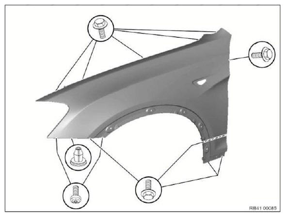
Release screws.
Replacing left rear side panel
Read contents of BODY, GENERAL.
STRIP DOWN VEHICLE
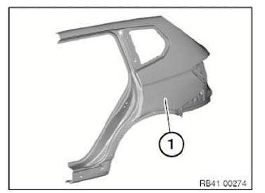
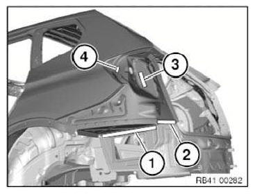
Procedure OBSERVE repair stage 2! Following new body parts are required :
- (1) Rear side wall
- Reinforcement plate, side sill
- Reinforcement plate, C-pillar
- Reinforcement plate, D-pillar
- Mounting nuts
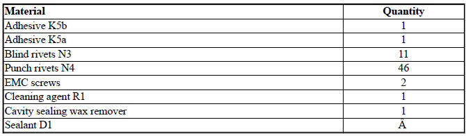
Following CONSUMABLES are required:
Removing side panel
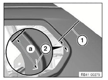
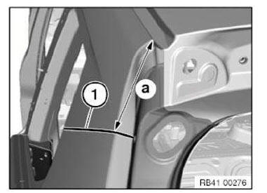
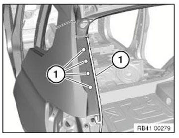
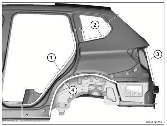
Mark dimension a for severance cut (1) on D-pillar.
Dimension a = approx. 75 mm from corner of mark (2).
Mark dimension a for severance cut (1) on D-pillar.
Dimension a = approx. 135 mm from corner of roof frame.
Carry out severance cut (1).
IMPORTANT: Cut outer panel only.
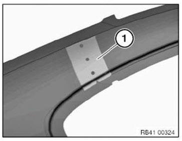
NOTE: In addition to the dimensions, the position of the separating cut can be determined with a TEMPLATE (1).
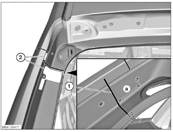
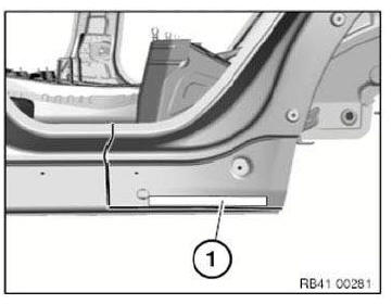
Mark severance cut (1) in accordance with dimension and cut.
Dimension a = approx. 60 mm from center point mounting bore for damper holder.
IMPORTANT: Cut outer panel only.
Severance cut (1) must be partially executed using a belt sander.
Open welded connections in areas (2).
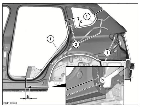
Mark severance cuts in accordance with specified dimensions and cut.
IMPORTANT: Cut outer panel only.
Compare position of severance cuts with REINFORCEMENT PLATES.
Dimension a = approx. 65 mm before center of 22 mm dia. hole.
Dimension b = approx. 20 mm from sill edge.
Dimension c = approx. 155 mm from side wall component edge.
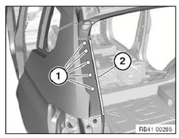
Open welded connections in areas (1).
Release side wall from cavity sealing (2).
Open welded connections in areas (1).
Take off side wall.
New part preparation
Mark severance cuts on the new part according to vehicle and cut.
Prepare REINFORCEMENT PLATES (bonded) at all severance cuts.
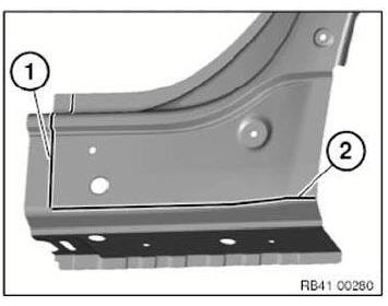
Mark severance cut (1) in accordance with vehicle and cut.
Mark severance cut (2) at sill edge and cut.
Mark further severance cuts in accordance with vehicle and cut.
D-pillar water channel severance cut area: Make an additional 2 shims (1) and (2) in the severance cut area.
NOTE: Before installing the side wall:
Coat shim (1) with adhesive and slide in.
Coat shim (2) with adhesive and secure with a punch rivet N4.
Adjust new part to fit and secure.
Set three 4.2 mm dia. holes for blind rivets in area (1).
In areas (1) to (4), set 4.2 mm dia. bore holes for blind rivets.
Remove new part again and deburr bore holes.
IMPORTANT: Do not grind/sand new part in area of bonding surfaces.
Installing side wall
Clean all bonding surfaces on vehicle, on the new part and on the reinforcement plates with cleaning agent R1.
Apply adhesive to reinforcement plates. Install reinforcement plates.
Apply adhesive in areas (1).
Apply sealant to CAVITY ACOUSTIC BAFFLES in areas (2).
Install side panel with a second person helping.
NOTE: When installing side panel, make sure there is sufficient adhesive on bonding surfaces.
After adjusting side wall to fit, tighten nuts of reinforcement plates.
Align side wall in areas of severance cuts and fix with gripping pliers.
Rivet side wall with blind rivets N3.
In areas (1) to (4) rivet side panel with punch rivets N4.
Rivet side wall with blind rivets N3.
In areas (1) and (2) rivet side panel with punch rivets N4.
Once the adhesive has hardened in area (1) and in the area of the side sill, fit one EMC SCREW in each area.
Stripping operations - replacing rear side panel, left
NOTE: Owing to the different engine variants and equipment specifications, not all the components are taken into consideration.
The following list basically represents the removal sequence.
- Disconnect negative battery cable
- Remove bumper trim panel
- Remove rear bumper guide middle (left side)
- Remove left bumper guide
- Remove tail panel cover at top
- Remove luggage compartment floor trim panel
- Remove left luggage compartment wheel arch panel
- Remove rear left side window
- Partially detach tailgate seal
- Release holder for damper
- Remove left rear light
- Remove trim panel for left roof pillar
- Remove left lock striker
- Remove rear left door sill cover strip
- Remove rear left rocker panel trim
- Remove left backrest side section
- Remove cover on C-pillar at bottom left
- Remove rear left door edge protection
- Remove rear left wheel arch cover
- Remove cover on rear wheel arch
- Remove trim panel for cover on left side member
- Remove rear left underbody panelling
- Remove rear left door
- Remove trim strip on left roof frame
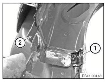
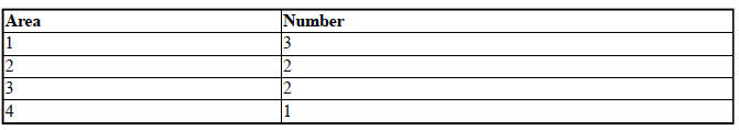
Undo latch mechanisms and remove rear bleeder (1).
Disconnect plug connections for control unit (2).
Remove bracket (3).
Remove insulating mat (4).
Installation note: The rear ventilation (1) must not be damaged. (watertightness).
All latch mechanisms must engage audibly.
 Rear trim panel
...
 Front side doors
...
Other materials:
BMW X3 (F25) Service & Repair Manual > Body and Frame: Body cavity sealing
It is only necessary to rewax or seal the affected area after repairing the
body.
Only BMW approved products may be used to comply with the six year warranty
against rust perforation.
These products protect cavities effectively and permanently against corrosion.
Their excellent coating a ...
