BMW X3 (F25) Service & Repair Manual: Propeller shaft assembly
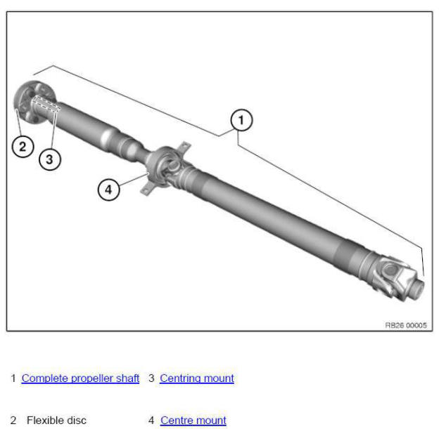
OVERVIEW (PROPELLER SHAFT FITTED, UNIVERSAL JOINT)
- Removing and installing front propeller shaft
- Removing and installing universal joint propeller shaft (inserted) completely
- Removing and installing/replacing front centring mount for propeller shaft
- Replacing center mount gaiter
- Replacing flexible disc for front propeller shaft
Removing and installing front propeller shaft
IMPORTANT: Do not move vehicle under its own drive power once propeller shaft has been removed.
IMPORTANT: On four-wheel drive vehicles with defective, non-engaging drive, it is imperative that the following information is taken account of.
Necessary preliminary tasks:
- Remove underbody protection at front and rear .
- Remove REINFORCEMENT PLATE .
Release screws.
Installation note: Replace ZNS bolts.
Slide propeller shaft towards rear and remove.
Installation note: Slide propeller shaft fully towards rear.
Sealing cup (1) must snap audibly into place and rest entirely on dust guard (2).
Removing and installing universal joint propeller shaft (inserted) completely
Special tools required:
- 00 9 120
- 00 9 130
- 33 0 080
- 33 5 070
IMPORTANT: On four-wheel drive vehicles with defective, non-engaging drive, it is imperative that the following information is taken account of.
IMPORTANT: Replacement of the sunk nut on the rear axle final drive is absolutely required! The sunk nut already has a screw locking.
After the propeller shaft has been screwed into the rear axle final drive (sunk nut), a hardening time of at least 2 hours is absolutely necessary.
The hardening time may be extended at lower temperatures! Failure to comply with these instructions may cause serious damage!
Necessary preliminary tasks:
- Remove complete exhaust system.
- Remove heat shields.
IMPORTANT:
Adhere without fail to the installation and bolt-tightening sequence.
installation sequence:
- Join propeller shaft to transmission
- Join propeller shaft to rear axle final drive
- Join center mount
Screw-fastening sequence:
- Insert nut
- Flexible disc to transmission
- Center mount
IMPORTANT:
To avoid buzzing sound after refitting the propeller shaft:
- The flexible disc connection (1) on the front at the propeller shaft must be marked in one plane with the flexible disc (2) and the three-bolt flange (3) before removal.
- During installation the three-bolt flange (3) must be forced back together again with the flexible disc (2) in the same position.
- Replace ZNS bolts and self-locking nuts.
Release screws.
Installation note:
- Replace ZNS bolts and self-locking nuts.
Installation note: Check centring mount.
If necessary, replace damaged CENTRING.
Grease centring mount.
Installation note: Tighten down screws/bolts to specified torque.
Secure angle of rotation special tool 00 9 120 with magnets 00 9 130 to vehicle underbody and screw down further according to angle of rotation.
Release screws (1).
Remove reinforcement plate (2).
Slacken screws (1) .
Using a suitable tool (2), secure propeller shaft at center universal joint against twisting.
Remove screws of center mount fully only after opening insert nut.
IMPORTANT: The bi-hexagonal flange nut must not be used for bracing.
Failure to comply with this instruction may result in serious damage to the rear axle final drive.
IMPORTANT: The sunk nut must be opened against direction of travel in clockwise direction.
If an attempt is made to open the sunk nut in direction of travel in clockwise direction, the sunk nut is automatically screwed in further and the insert collar of the 12-edge flange nut is severely damaged.
If the insert collar of the flange nut was damaged, the propeller shaft can no longer be secured using a new sunk nut and the rear axle differential must be replaced.
Release insert nut against direction of travel in clockwise direction with special tool 33 0 080 and 33 5 070 .
Remove retaining clip (1) and gasket (2).
Installation note: Retaining clip and gasket must be replaced.
Remove insert nut (1).
Installation note: Insert nut must be replaced.
The sunk nut is equipped with a screw locking.
Prior to the first journey, a minimum hardening time of 2 hours must be complied with.
Failure to comply with these instructions may cause serious damage! Before installing propeller shaft: Clean insert collar (1) on flange nut and gearing on bevel pinion (2).
Fill insert collar (1) with grease.
Clean thread (1) of joint hub to remove adhesive residues.
Clean hub teeth (2), then coat with grease.
IMPORTANT: Thread of joint hub must not be fouled with grease.
Place flange nut (1) with gasket in insert collar of flange nut.
Install retaining clip (2).
IMPORTANT:
Adhere without fail to the installation and bolt-tightening sequence.
Installation sequence:
- Join propeller shaft to transmission.
- Join propeller shaft to rear axle final drive.
- Join center mount.
Screw-fastening sequence:
- Insert nut.
- Flexible disc to transmission.
- Center mount.
IMPORTANT: The bi-hexagonal flange nut (2) must not be used for bracing.
Failure to comply with this instruction may result in serious damage to the rear axle final drive.
Insert nut must be screwed into place within 5 min .
Slide output shaft (1) to the limit position onto insert nut and secure.
Secure output shaft at center universal joint against turning with a mounting lever.
Removing and installing/replacing front centring mount for propeller shaft
Special tools required:
- 00 5 500
- 11 1 310
- 11 2 030
Necessary preliminary tasks:
- Remove PROPELLER SHAFT.
Completely fill centring bore hole (1) with viscous grease.
Drive special tool 11 1 310 with a plastic hammer into centring bore hole.
The centring bearing (1) is forced out of the propeller shaft by the pressure on the grease filling.
If necessary, top up grease repeatedly.
NOTE: To drive out the bearing, you can also fill the centring bore hole with water instead of grease.
Installation note: Remove grease or water from mount bore.
Drive in centring mount (1) with special tools 11 2 030 and 00 5 500 into propeller shaft (observe protrusion).
Grease centring mount.
Installation note: Observe protrusion A = 4+2 mm of centring (1).
Replacing center mount gaiter
Necessary preliminary tasks:
- Remove PROPELLER SHAFT.
NOTE: The propeller shaft is balanced.
The front and rear propeller shafts must be reassembled in the same position.
Detach gaiter (1) from groove (2).
Mark front propeller shaft (3) and rear propeller shaft (4) in one plane.
Pull apart propeller shaft.
Installation note: If necessary, insert new clamping ring (1) into front propeller shaft (2).
Release gaiter (1) with screwdriver from groove (2) and pull off over longitudinal splines.
Installation note: Apply an even coating of grease to longitudinal splines on shaft.
Observe markings and force front propeller shaft onto longitudinal splines (markings must be flush).
Push gaiter (1) during installation into groove (2) and make sure it is firmly fitted.
Replacing flexible disc for front propeller shaft
Necessary preliminary tasks:
- Remove PROPELLER SHAFT at transmission and center bearing.
- Remove complete propeller shaft (F06, F10, F12, F13 - S63).
NOTE: To protect universal joints, tie back propeller shaft in area of center mount.
Release screws and remove flexible disc (1) from propeller shaft.
Tightening torque and angle of rotation 26 11 2AZ .
IMPORTANT: Replace ZNS bolts and self-locking nuts.
NOTE: On the F06, F10, F12, F13 - S63 a silicone flexible disc is installed instead of the conventional rubber part flexible disc.
Installation note: During installation arrows (2) on circumference of flexible disc must point to flange arms (3).
NOTE: Instead of conventional rubber flexible disks, F series also use aluminium flexible discs, which are also called EGG (constant velocity joints).
Installation note: Check centring mount.
Replace damaged CENTRING MOUNT.
Grease centring mount.
 Propeller shaft, general
PROPELLER SHAFT DEFLECTION ANGLES
IMPORTANT:
Specifications on propeller shaft deflection angles for the F series are only possible on request
...

Other materials:
BMW X3 (F25) Service & Repair Manual > Transmission: Extension housing, bearings, seal
REPLACING OUTPUT FLANGE RADIAL SHAFT SEAL (GA8HP45Z) (AWD)
Special tools required:
23 0 490
23 3 220
IMPORTANT:
After completion of repair work, check TRANSMISSION OIL LEVEL .
Use only the approved TRANSMISSION OIL .
Failure to comply with this requirement will result in serious dam ...
