BMW X3 (F25) Service & Repair Manual: Troubleshooting
- Battery replacement information
- Butt connector for repairing a plug connection
- Contents of engine electrical system general
- Instructions for welding work (overload protection of control units)
- Instructions for removal and replacement of control units
- Instructions for working on the ignition system
- Notes for disconnecting and connecting battery
- Notes for opening contacts and locks of different plug contact systems
- Notes on handling wiring harnesses and cables
- Notes/information on start assistance (jump starting)
- Safety information for working on vehicles with automatic engine start-stop function (msa)
Battery replacement information
A vehicle battery is constructed for the installation location and the individual power requirements of the particular vehicle. These individual power requirements depend on the motorization and different types of equipment. The individually assigned vehicle battery is the ideal compromise between the power requirements of the vehicle electrical system and the weight and service life of the vehicle battery.
Vehicles with the automatic engine start-stop function or particular engine types and optional equipment are equipped with a special vehicle battery (AGM battery), since only this battery type can provide elevated power requirements over the extended service life. Installing a different vehicle battery can cause problems with vehicle electronics, can reduce functions or can cause leakage of battery acid.
In the event of an accident where the airbags are deployed in vehicles with a vehicle battery in the luggage compartment, the electrical connection between the vehicle battery and the trigger is automatically disconnected through pyrotechnics. This prevents possible short-circuiting.
Proper operation of all of these safety and convenience functions requires a battery that conforms with specifications and that is properly registered in vehicles with energy management systems (IBS, power module).
Vehicles with energy management systems (IBS, power module): Register battery replacement
The vehicle electrical system is informed about the vehicle battery characteristic data, such as type, size, age and current power capacity. Therefore, there will always be only one work scope provided that is permitted by the current status of information.
If the performance readiness drops below a defined minimum, a Check Control message will be generated to advise the driver that the battery must be replaced.
When installing a new vehicle battery, the battery must be registered and thus must also be registered with the vehicle electrical system.
NOTE: Only this registration/logon will ensure that the corresponding Check Control message will go out again.
Diagnosis system:
Register battery replacement
- Service functions
- Body
- Voltage supply
- Register battery replacement
When retrofitting, a more powerful battery may be used. Standard batteries may always be replaced by AGM batteries with the same specifications.
When installing a battery of a different size or a different battery type, this change in vehicle data must be programmed into the vehicle data in accordance with specifications.
Programming system:
- Battery retrofitting
Butt connector for repairing a plug connection
Special tools required:
- 61 0 300
- 61 4 340
- 61 0 240
IMPORTANT:
- Identify cause of damage (e.g. sharp-edged body components, faulty electrical loads, jammed mechanisms, corrosion caused by ingress of water, etc.).
- Read out fault memory
- Eliminate cause of damage.
- Disconnect battery negative terminal
- Make sure that no safety-related system according to circuit diagram (e.g. antilock braking system, active rear-axle kinematics, airbags, etc.) are influenced. Otherwise replace faulty wiring harness or use repair cable (sourcing reference: BMW Parts Department)
- Carry out function test and read out fault memories again
- Eliminate new faults if applicable and clear fault memories
NOTE: The repair range IV for vehicle electrical system contained the required special tools and individual parts for retrofitting and repair work with the aid of fan connectors.
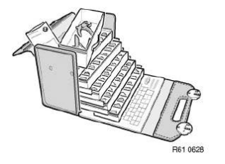
Choose repair kit.
Example: Repair kit, circular connector system D 2.5.
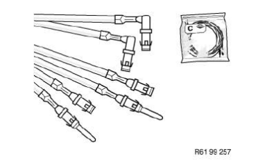
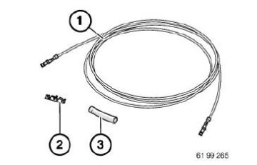
Remove following parts:
- Pre-packaged end of cable with requisite wire cross-section
- Crimp connector for selected wire cross-section
- Shrink-fit hose
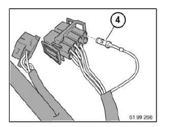
Open secondary lock on housing.
Mark damaged contact (4) with socket number of housing and press it out of housing using appropriate special tool contained in special tool set 61 0 300 ).
See repair instructions
NOTES FOR OPENING CONTACTS AND LOCKS of different plug contact systems.
IMPORTANT:
- Check maximum length of repair cable
- If more than one wire is to be repaired, the individual interfaces must be offset so that the wiring harness is not too thick at the repaired point.
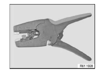
Adhere to following procedure:
- Cut off wire with faulty contact at point which is easily accessible
- Strip insulation from end of wire at wiring harness end
- Cut preassembled wire end to length and strip insulation
Refer also to repair instruction:
CUTTING TO LENGTH AND STRIPPING INSULATION FROM CABLES
Crimp butt connector on preassembled wire end.
Special tools:
- 61 4 340 (0.35 - 2.5 sq mm)
- 61 0 240 (4.0 - 6.0 sq mm)
See repair instructions
CRIMPING ON STOP PARTS
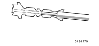
Push shrink-fit hose (8) onto free wire end.
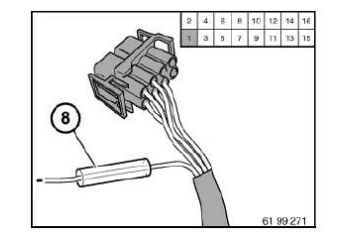
Crimp unused wire end to butt connector.
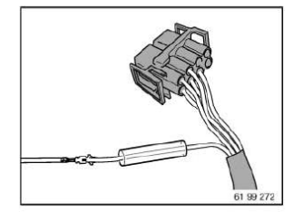
Pull shrink-on sleeve over butt connector.
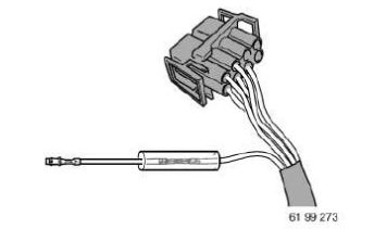
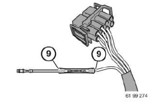
IMPORTANT: Do not burn shrink-on sleeve.
With hot air blower, shrink the shrink-on sleeve on both sides (9) of shrink-fit hose until glue emerges uniformly all round.
Insert contact in housing.
Close secondary lock on housing.
Contents of engine electrical system general
General Information
- WORKING ON IGNITION SYSTEM
- REMOVING AND INSTALLING ELECTRONIC CONTROL UNITS
- WELDING WORK (overload protection of control units)
- Disconnecting and connecting battery
- DISCONNECTING AND CONNECTING TEST EQUIPMENT
- COMPONENT INSPECTION
- EXTERNAL JUMP-STARTING AID
- Compression testing
HANDLING COMPONENTS AFTER FLOOD DAMAGE
Flood damage can occur if the permissible fording depth of a vehicle is exceeded. Ingress of water can cause damage to the engine (water shock) or components.
Because dirt particles generally enter into the component with the water (e.g. starter motor, wiring harness), the components need to be thoroughly inspected.
Residual moisture in the components leads to corrosion (increased contact resistance in the component), which can lead to a component failure at a later time.
If water ingress into the electrical components cannot be ruled out, it is recommended to replace the component to ensure correct functioning through the vehicle lifetime.
Instructions for welding work (overload protection of control units)
CAUTION: Follow instructions for body repairs.
When performing welding work on installed control units, to avoid any defects in the electronic control units, observe the following steps:
- Observe instructions for disconnecting and connecting battery.
- Detach terminal of battery negative lead from car battery and second battery if fitted. Cover negative terminal posts.
- If welding is to be performed near the battery/batteries, first remove battery/batteries from vehicle (flying sparks - combustion of explosive gas).
- Fit return clamp on welding unit as close as possible to welding point (maximum distance approx. 1 m).
- Never connect return clamp to ground pin on body which has ground wires attached!
INSTRUCTIONS ON COMPONENT TESTING
NOTE:
- During all inspections and work on engine electrics and electronics, always observe safety regulations and accident prevention specifications.
- Always disconnect connectors of control units or components before checking electric wires.
Testing Aids:
- Schematics, refer to Diagnosis Information System (DIS).
- Only ever use test lines, adapters, terminals and test tips manufactured by specialists, refer to Diagnosis Information System, Repair Manual.
- The inspection values for component testing are located in the Diagnosis Information System (DIS).
- For further technical information, refer to Technical Data.
INSTRUCTIONS FOR CONNECTING AND DISCONNECTING TEST UNITS
When connecting and disconnecting:
- Service Tester
- testing devices
- test leads and
- when replacing control units
it is essential to turn off the ignition!
FOLLOW INSTRUCTIONS FOR REMOVING AND INSTALLING ELECTRONIC CONTROL UNITS.
Follow operating instructions for testing devices.
Make sure that connected test leads cannot make contact with rotating parts (e.g.: fans, ribbed V-belts, etc.).
Instructions for removal and replacement of control units
IMPORTANT:
- Disconnecting the vehicle battery will cancel the fault memories of control units.
Consequently, before disconnecting the car's battery, always interrogate the fault memories. Investigate stored faults and, once any faults have been remedied, cancel the fault memory.
- Control unit plugs should only ever be connected and disconnected while the ignition is turned off.
- The removal and installation of components, relays, fuses etc. can cause faults to be stored in fault memories capable of self diagnosis. Always interrogate the fault memories after completing work on the electrical system.
- Investigate stored faults and, once any faults have been remedied, cancel the fault memory.
- If necessary, initialize power window regulator Initialize power window regulator
On replacement of the DME/DDE control unit note the following:
-
In every case use the diagnosis system to read out the hardware/software version of the corresponding
control unit.
Comply with the diagnosis system instructions for the encoding and programming work operations.
On vehicles with an electronic immobiliser, comply with the diagnosis system instructions.
- In every control unit certain mean values are stored that are the basic values. The control unit receives different input values according to the engine condition. The teachable system compares the input values against the stored basic values and then forms the associated control commands. The control commands are forwarded to the corresponding actuators.
- When the DME control unit is de-energized for a long period (over one hour), the teachable system then loses the stored values. When a deleted control unit is returned to service or a new control unit is installed, the teachable system itself must read in and store the input value of the associated engine as new basic values.
- This process may cause uneven idle and faults in coasting mode after starting. Depending on the engine characteristics, it may take some time until all values have been compared with the engine condition.
- Therefore, comply with the following procedure before replacement or reinstallation of a DME/DDE control unit is carried out:
- If possible, bring the engine up to its operating temperature prior to replacement of the control unit.
- Change control units and drive the vehicle with changing engine speeds.
Instructions for working on the ignition system
CAUTION: Always switch off ignition before working on ignition system.
Use only test leads which have been approved and belong to these testing instruments (e.g. DIS Tester).
Comply with operating instructions of the respective testing instrument used.
Comply with the country-specific safety regulations.
Never touch components under current with engine running! Comply with instructions of DIS tester.
Do not connect any suppression capacitors or inspection lamps to terminal 1 on the ignition coil.
Terminal 1 of ignition coil must not be connected to ground or battery positive lead.
If an alarm system is subsequently installed, lead of terminal 1 must not be used for start prevention.
When working on ignition system, always disconnect supply leads to ignition coils.
High tension! - High tension!
IMPORTANT: Hazardous voltages occur at:
- Ignition lead
- spark-plug connectors
- spark plugs
- Ignition coil (high voltage at terminal 4 is approx. 40 kV)
- Lead of terminal 1 from ignition coil to DME control unit (high voltage approx. 350 V)
Notes for disconnecting and connecting battery
Observe SAFETY INFORMATIONS FOR HANDLING VEHICLE BATTERY .
Before disconnecting battery:
Turn off the ignition and other electrical loads/consumers to prevent sparking when reconnecting.
NOTE: If the ignition is not turned off when the battery is disconnected, fault memories may be set in some control units.
IMPORTANT:
- There is a danger of mixing up battery cables: If the battery positive and negative leads are the same color and you are in doubt, follow the polarity to the battery, then mark and cover the leads.
- The on-board computer and clock may lose your data.
General notes on disconnecting battery:
- Do not disconnect battery leads and leads from alternator and starter motor while engine is running.
- Disconnect terminal of BATTERY EARTH LEAD from the battery. Cover battery negative terminal(s) and secure.
- Disconnect both battery earth leads in version with auxiliary battery. Cover battery negative terminal(s) and secure.
- When work is carried out on the electrical system, faults may be caused in the fault memories of some control units when the battery is connected.
- When installing battery terminal
Only lead AGM battery:
- On vehicles with IBS at negative battery terminal:
Do not under any circumstances pull/lever off pole shoes by force.
Do not under any circumstances release socket-head cap screw of IBS.
After connecting battery:
IMPORTANT: The scope of application of some systems may be restricted after an open circuit.
Personal Profiles may also be lost.
Settings or activations must be carried out, depending on the equipment specification.
For example:
- Activate slide/tilt sunroof.
- Activate power window .
Refer to the diagnosis system for further vehicle-specific information.
Notes for opening contacts and locks of different plug contact systems
Special tools required:
- 61 0 300
- 61 0 400
- 61 1 100
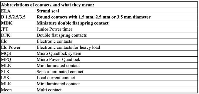
IMPORTANT: The contacts can be changed on ultrasonically welded connectors (1).
Ultrasonically welded connectors (1) must be replaced completely.
Ultrasonic-welded connectors (1) can be identified by the welds (2) on their longitudinal side.
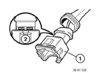
NOTE: Special tools referred to in the repair instructions below are contained in the following special tool sets:
- Unlocking and pressing-off tool 61 1 150 is replaced as of 09/2005 by 61 0 300 (BMW) and 61 0 400 (MINI)
- Release and pressing-off tool 61 1 100 (engine)
Repair instructions for opening connector housings and removing contacts of different connector systems:
Connector system D 1.5/D 2.5:
- CIRCULAR CONNECTORS, 7- OR 8-PIN, SYSTEM D 2.5
- CIRCULAR CONNECTORS, 13-PIN, SYSTEM D 2.5
- CIRCULAR CONNECTORS, 20-PIN, SYSTEM D 2.5
- CIRCULAR CONNECTORS, 4-, 7-, 10-, 12- OR 25-PIN, SYSTEM D 1.5/D 2.5
- IN-LINE CONNECTORS, 15-PIN, SYSTEM D 2.5
- IN-LINE CONNECTORS, 8-, 12-PIN, SYSTEM D 2.5
- IN-LINE CONNECTORS, 30-PIN, SYSTEM D 2.5
- IN-LINE CONNECTORS, 20-PIN, SYSTEM D 2.5
Connector system JPT/MDK/DFK:
- IN-LINE CONNECTORS, 2-PIN, SYSTEM JPT ELA
- IN-LINE PLUGS, 2-PIN, SYSTEM MDK 3 PLUS 2.8
- IN-LINE PLUGS, 4-PIN, SYSTEM DFK ELA
Connector system Elo/Elo Power:
- INLINE PLUGS, 4-, 10-PIN, SYSTEM ELO
- IN-LINE CONNECTORS, 6- TO 50-PIN, SYSTEM ELO
- INLINE PLUGS, 3-, 6-PIN, SYSTEM ELO-POWER 2.8
Connector system LSK:
- CONNECTOR HOUSING LSK CONTACT
Connector system MQS/MPQ:
- INLINE CONNECTORS, 6-, 8-PIN, SYSTEM MQS
- INLINE PLUGS, 2-PIN, SYSTEM MPQ 2.8
- CONTROL UNIT CONNECTORS, 25-, 35-, 55-, 83-, 88-PIN
- IN-LINE PLUGS, 24-PIN, HYBRID SYSTEM MQS/MPQ
- SOCKET HOUSING 42-, 43-PIN, HYBRID SYSTEM MQS/MPQ
- SOCKET HOUSINGS 2X21-, 2X27-
- PIN, HYBRID SYSTEM MQS/MPQ, ELO/ELO POWER
- IN-LINE CONNECTORS, 30-PIN, HYBRID SYSTEM MQS/MPQ
- SOCKET HOUSINGS, 5-, 8-PIN, SYSTEM MQS/MPQ
- SOCKET HOUSING (RADIO CONNECTOR), HYBRID SYSTEM MQS/MPQ
Notes on handling wiring harnesses and cables
The following applies in general:
To avoid damage, observe the following instructions:
- Avoid compressive and tensile loads
- To ensure professional repairs, perform repair work only with BMW-approved or recommended special tools and spare parts
- Make sure cables are laid without kinks or abrasions
- Ensure non-contacting routing at sharp-edged body parts; use edge protection if necessary
- Secure additionally laid cables/leads with cable ties
The following additionally applies
Shielded cables
Contact points in the shield can cause problems with regard to noise radiation and interference immunity.
Consequently, distinctions have to be drawn between the following types:
Coaxial cable
- Shielded RTK031 coaxial lines may only be repaired with special crimping tools.
CVBS cables
- CVBS cables may not be repaired.
- CVBS cables must be replaced in their entirety.
HSD cables
- HSD cables may not be repaired.
- HSD cables must be replaced in their entirety.
Fibre-optic cables:
NOTE: Optical fibre cables are colored differently as follows:
- Green = MOST (M edia O riented S ystems T ransport) optical fibre
- Yellow = ISIS (I ntelligent S afety I ntegration S ystem) optical fibres
- Orange=repair fibre-optic cables
IMPORTANT:
- Optical fibres are permitted to show only one junction point (bridge). Replace optical fibres if necessary
- Smallest permissible bending radius is 25 mm
- Avoid effects of heat ≥ 85 º
Treating cables and fibre-optic cables .
FlexRay:
It is possible to repair the FlexRay. In the event of damage, the cables can be joined with conventional BUTT CONNECTORS AND HEAT-SHRINK TUBING.
NOTE:
- FlexRay lines may only reveal one separation point (bride); renew complete line if necessary.
- The cable is a twisted cable. If possible, maintain twisted cable after repair.
Airbag lines:
REPAIRING AIRBAG CABLES
Notes/information on start assistance (jump starting)
Do not start the engine with help of starting sprays.
Preparation:
Conform with the following when starting the engine with a jump starting cable.
- Ensure that the jump starting cable wires are of appropriate cross-section size.
- Only use fuse-protected jump starting cables.
- Check whether the current-supplying battery has 12 V voltage.
- If the engine is started from the battery of another vehicle, ensure that there is no contact between the bodies of both vehicles.
IMPORTANT: Never touch electrically live ignition system components: high voltage - danger of injury!
If the battery in the vehicle supplying power is weak, start the engine of this vehicle and let it run at idling speed.
Operation: It is essential to conform to the procedures so as to avoid injury to persons or damage to parts.
- Automatic transmission: select drive position "P", apply parking brake.
- Manual transmission: move gear lever to neutral position, apply parking brake.
- Ensure that the jump leads cannot get caught in rotating parts, e.g. fan.
- First connect both positive poles of the batteries with one jump starting cable (red).
- Use the battery positive terminal in the engine compartment for vehicles with the battery in the luggage compartment.
- Then use the second jump starting cable (black) to connect the negative post of the current-supplying battery with the earth/ground point (not the negative pole or the body) of the vehicle to be started.
IMPORTANT: Do not connect the second jump starting cable (black) with the negative pole of the battery in the vehicle to be started. Produced gas could be ignited by sparks.
Risk of explosion! After the engine of the vehicle to be started has fired, first disconnect the jump starting cable between the negative pole and the earth/ground point. Then remove the starting cable from the positive poles.
Safety information for working on vehicles with automatic engine start-stop function (msa)
WARNING: If the engine hood/bonnet contact is pulled upwards (workshop mode), the information "switch closed" is output. The automatic engine start-stop function is active.
An automatic engine start is possible.
Observe safety precautions when working on MSA vehicles.
Before carrying out practical work on the engine, always ensure that the MSA functionality is deactivated so as to prevent automatic engine starting while work is being carried out in the engine compartment.
MSA function is deactivated by:
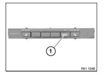
- Deactivate MSA by means of button (1) in passenger compartment
- Open seat belt buckle and driver's door
Open engine bonnet/hood and ensure that engine hood/bonnet contact is not in workshop mode
- Workshop mode
A = 10 mm - Basic setting (engine hood/bonnet open)
B = 7 mm
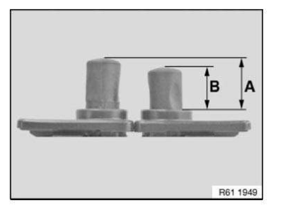
To make sure that the engine hood/bonnet contact is at the basic setting, if necessary press the hood/bonnet contact up to the limit position before starting work and slowly release.
When working with diagnosis tools:
- Observe instructions in diagnosis tool
 Description
WARNING: Vehicles are equipped with air bag supplemental restraint
system. Before attempting any repairs involving steering column, instrument
pan ...
Other materials:
BMW X3 (F25) Service & Repair Manual > Transmission: Checking transmission fluid level
4.0 CHECKING TRANSMISSION FLUID LEVEL
Due to the substantial expansion of transmission fluid when heated it is only possible to measure the oil level
correctly at specified oil temperatures (after driving a distance of about 12 mi./20 km).
ZF 3HP AND 4HP
Due to the substantial expansion of t ...

