BMW X3 (F25) Service & Repair Manual: Engine wiring loom
- Removing and installing/replacing engine sensor system module 2 wiring harness (N20)
- Removing and installing/replacing engine sensor system wiring harness module 1 (N20, N26)
- Replacing section of wiring harness for engine (N47D20 O1)
- Replacing section of wiring harness for injectors (N47 D20 O1)
- Replacing the wiring harness section for the engine transmission module (N20)
- Replacing wiring harness section for valvetronic servomotor (N20, N26)
- Replacing wiring harness section for engine (N20)
- Replacing wiring harness section for engine (N55)
- Replacing wiring harness section for ignition and injectors (N20)
- Replacing wiring harness section for ignition and injectors (N55)
Removing and installing/replacing engine sensor system module 2 wiring harness (N20)
IMPORTANT: Read and comply with notes on PROTECTION AGAINST ELECTROSTATIC DISCHARGE (ESD PROTECTION) .
Necessary preliminary tasks:
- Read out the fault memory of the DME control unit.
- Switch off ignition.
- Remove intake PLENUM .
- Release the COOLANT THERMOSTAT and set on the side. Do not drain the coolant and do not release the coolant hose.
- REMOVE bottom clean air pipe.
- Remove ENGINE VENTILATION LINE .
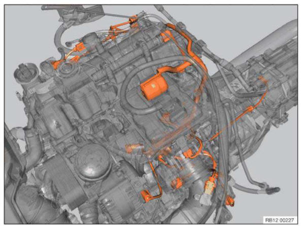
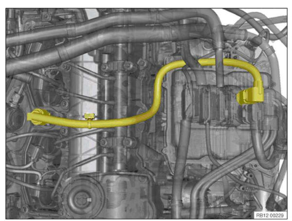
Overview of engine wiring harness sensor system module 2.
Release screws (1).
Release cable channel (2).
Installation note: Reconnect the earth connection.
Release wiring harness if necessary from existing clips and clamps.
Feed out wiring harness and remove.
Installation note:
Check wiring harness installation arrangement.
Check plug connections for correct fit.
Check stored fault message.
Clear diagnostic fault entries from fault memory.
Removing and installing/replacing engine sensor system wiring harness module 1 (N20, N26)
IMPORTANT: Read and comply with notes on PROTECTION AGAINST ELECTROSTATIC DISCHARGE (ESD PROTECTION) .
Necessary preliminary tasks:
- Read out the fault memory of the DME control unit.
- Switch off ignition.
- Remove INTAKE PLENUM .
Overview, engine sensor system wiring harness module 1.
Release wiring harness if necessary from existing clips and clamps.
Feed out wiring harness and remove.
Installation note:
Check the wiring harness installation arrangement.
Check that the plug connections are correctly fitted.
Check stored fault message.
Clear diagnostic fault entries from fault memory.
Replacing section of wiring harness for engine (N47D20 O1)
IMPORTANT: Read and comply with notes on protection against electrostatic damage ESD protection).
Necessary preliminary work:
- Read out the fault memory of the DDE control unit.
- Switch off ignition.
- Disconnect BATTERY EARTH LEAD .
- Remove INTAKE FILTER HOUSING .
- Remove INTAKE PORT .
- Remove rear acoustic cover.
- Remove sound insulation on injectors.
- Remove front UNDERBODY PROTECTION .
Release screws (1).
Detach coolant hose from cover of electronics box.
Remove electronics box cover (3).
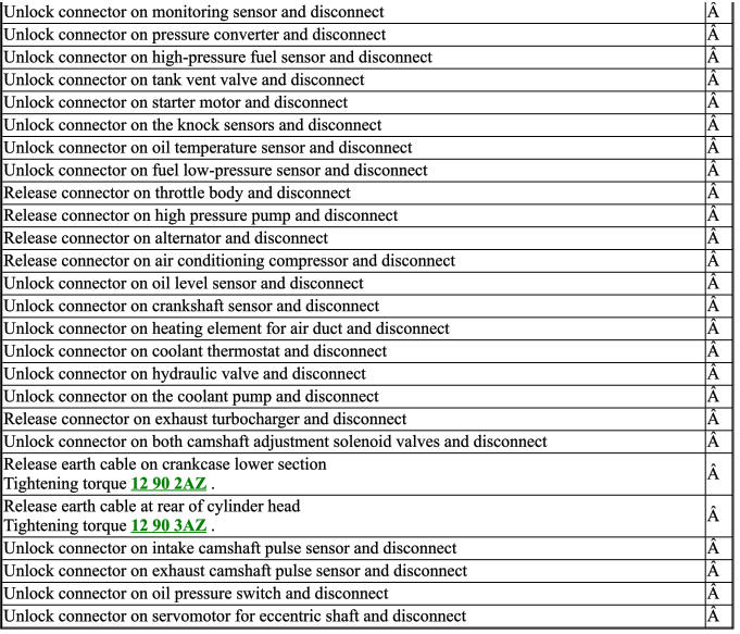
Unlock all connectors (1) from control unit and disconnect.
Detach rubber grommets (2) from electronics box. Place wiring harnesses to the side.
Installation note:
Make sure grommets are correctly fitted (watertightness).
Pull out fasteners (1) in direction of arrow.
Push back sockets (2) and detach engine wiring harness from connector housing.
Release screw (1).
Release cable channel (2).
Release wiring harness from clips and clamps.
Feed out wiring harness and remove.
Installation note:
Check wiring harness installation arrangement.
Check plug connections for correct fit.
Check stored fault message.
Delete fault memory.
Replacing section of wiring harness for injectors (N47 D20 O1)
IMPORTANT: Read and comply with notes on PROTECTION AGAINST ELECTROSTATIC DAMAGE (ESD PROTECTION) .
Necessary preliminary work:
- Read out the fault memory of the DDE control unit.
- Switch off ignition.
- Disconnect BATTERY EARTH LEAD .
- Remove INTAKE FILTER HOUSING .
- Remove rear acoustic cover.
- Remove sound insulation on injectors.
- Partially release WIRING HARNESS for engine.
Release screws (1).
Detach coolant hose from cover of electronics box.
Remove electronics box cover (3).
Unlock all connectors (1) from control unit and disconnect.
Detach rubber grommets (2) from electronics box. Place wiring harnesses to the side.
Installation note:
Make sure grommets are correctly fitted (watertightness).
Release retaining element (1) in direction of arrow.
Press back socket (2) and remove wiring harness for injectors.
Unlock plugs (1) on injectors and disconnect. Release wiring harness from cylinder head cover, feed out and remove.
NOTE: Check wiring harness installation arrangement.
Check plug connections for correct fit.
Reassemble the vehicle.
Read out the fault memory of the DDE control unit.
Check and rectify stored fault messages.
Delete fault memory.
Replacing the wiring harness section for the engine transmission module (N20)
IMPORTANT: Read and comply with notes on PROTECTION AGAINST ELECTROSTATIC DISCHARGE (ESD PROTECTION) .
Necessary preliminary tasks:
- Read out the fault memory of the DME control unit.
- Switch off ignition.
- Remove intake PLENUM .
- Remove rear UNDERBODY PROTECTION .
- Remove cross member .
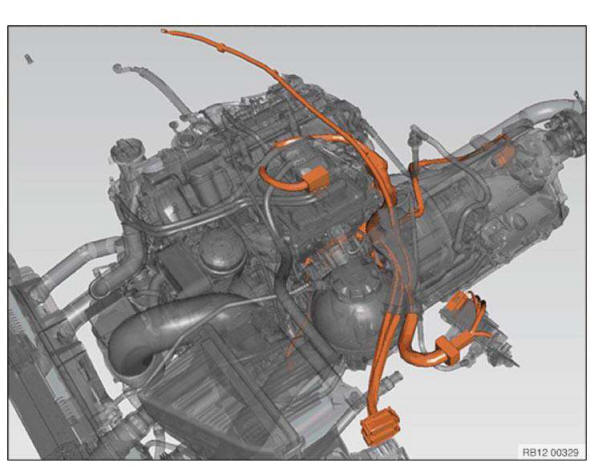
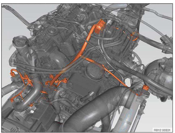
Overview of wiring harness section for engine transmission module (graphic shows wiring harness for vehicles with automatic transmission and four-wheel drive).
Detach all connectors from Power Distribution Module (1). Release wiring harness from bulkhead.
Disconnect plug connection (2).
Release screws (3) and lay wiring harness to one side.
Release wiring harness if necessary from existing clips and clamps.
Feed out wiring harness and remove.
Installation note:
Check wiring harness installation arrangement.
Check plug connections for correct fit.
Check stored fault message.
Clear diagnostic fault entries from fault memory.
Replacing wiring harness section for valvetronic servomotor (N20, N26)
IMPORTANT: Read and comply with notes on PROTECTION AGAINST ELECTROSTATIC DISCHARGE (ESD PROTECTION) .
Necessary preliminary tasks:
- Read out the fault memory of the DME control unit.
- Switch off ignition.
- Remove ACOUSTIC COVER
Undo wiring harness section for Valvetronic servomotor on DME control unit and Valvetronic servomotor and pull off.
Undo, feed out and remove wiring harness section from clamps.
Installation note:
Check wiring harness installation arrangement.
Check plug connections for correct fit.
Check stored fault message.
Clear diagnostic fault entries from fault memory.
Replacing wiring harness section for engine (N20)
IMPORTANT: Read and comply with notes on PROTECTION AGAINST ELECTROSTATIC DISCHARGE (ESD PROTECTION) .
Necessary preliminary tasks:
- Read out the fault memory of the DME control unit.
- Switch off ignition.
- Remove intake PLENUM .
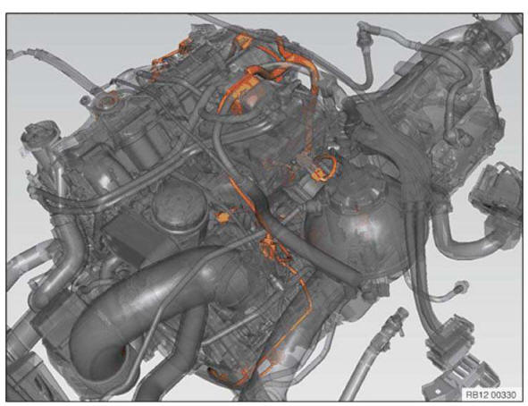
Overview, engine sensor system wiring harness module 1.
Release wiring harness if necessary from existing clips and clamps.
Feed out wiring harness and remove.
Installation note:
Check wiring harness installation arrangement.
Check plug connections for correct fit.
Check stored fault message.
Clear diagnostic fault entries from fault memory.
Replacing wiring harness section for engine (N55)
IMPORTANT: Aluminum screws/bolts must be replaced each time they are released .
Aluminum screws/bolts are permitted with and without color coding (blue).
For reliable identification: Jointing torque and angle of rotation must be observed without fail (risk of damage) .
IMPORTANT: Read and comply with notes on PROTECTION AGAINST ELECTROSTATIC DAMAGE (ESD PROTECTION) .
Necessary preliminary work:
- Read out the fault memory of the DME control unit.
- Switch off ignition.
- Disconnect BATTERY EARTH LEAD .
- Remove sound insulation at the rear of the engine.
- Remove intake PLENUM .
- Partially detach WIRING HARNESS for injectors and ignition coils.
- Remove CLEAN AIR PIPE .
- Remove FAN COWL .
- Remove front UNDERBODY PROTECTION .
Detach all connectors from Power Distribution Module (1). Release wiring harness from bulkhead.
Disconnect plug connection (2).
Release screws (3) and lay wiring harness to one side.
Release screws (1).
Unclip upper part of cable channel (2) and expose the wiring harnesses.
Unlock all connectors (1) from control unit and disconnect.
Installation note: Make sure grommets are correctly fitted (watertightness).
Release screws (1) below cable channel (2).
Replace aluminum screws.
Release screws (1).
Release cable channel (2).
Installation note:
Reconnect the earth connection.
Replace aluminum screws.
Release wiring harness if necessary from existing clips and clamps.
Feed out wiring harness and remove.
Installation note:
Check wiring harness installation arrangement.
Check plug connections for correct fit.
Check stored fault message.
Delete fault memory.
Replacing wiring harness section for ignition and injectors (N20)
IMPORTANT: Read and comply with notes on PROTECTION AGAINST ELECTROSTATIC DISCHARGE (ESD PROTECTION) .
Necessary preliminary tasks:
- Read out the fault memory of the DME control unit.
- Switch off ignition.
- Remove ACOUSTIC COVER
- Remove the PRESSURE CONVERTER for the exhaust turbocharger
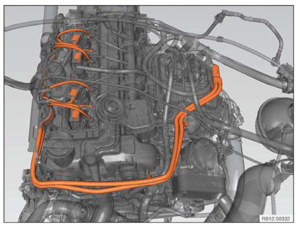
Overview of wiring harness section for ignition and injectors.
Unlock and remove connector (1) from control unit.
Release wiring harness from clamps (1).
NOTE: This procedure is applicable to all cylinders.
Unlock and disconnect connector (1) at injectors.
Slacken nut (1) and remove ground cable (3).
NOTE: This procedure is applicable to all cylinders.
Release connector catch (1) at ignition coil (2) and pull off connector.
Unlock retaining lug (1) in direction of arrow.
Pull cable channel (2) from cylinder head cover.
Pull out and remove wiring harness section for injectors and ignition coils.
NOTE: Check stored fault messages.
Clear diagnostic fault entries from fault memory.
Replacing wiring harness section for ignition and injectors (N55)
IMPORTANT: Read and comply with notes on PROTECTION AGAINST ELECTROSTATIC DAMAGE (ESD PROTECTION) .
Necessary preliminary work:
- Read out the fault memory of the DME control unit.
- Switch off ignition.
- Disconnect BATTERY EARTH LEAD .
- Remove IGNITION COIL COVER.
- Remove CLEAN AIR PIPE .
- Remove REAR IGNITION COIL COVER.
Unlock rear plug (1) from the control unit and disconnect.
Release rear wiring harness from intake plenum.
Release nuts (1) and remove earth cable.
Unlock all connectors from ignition coils and injectors and detach.
Unclip wiring harness (2), feed out and remove.
NOTE: Check stored fault messages.
Delete fault memory.
 Starter lead
...

Other materials:
BMW X3 (F25) Service & Repair Manual > Suspension: Approved final drive oils for front and rear axle final drives with and
without limited slip or viscous coupling
2.0 APPROVED FINAL DRIVE OILS FOR FRONT AND REAR AXLE FINAL
DRIVES WITH AND WITHOUT LIMITED SLIP OR VISCOUS COUPLING
LIMITED SLIP DIFFERENTIALS
With the introduction of the Z3 roadster a new synthetic final drive oil for all vehicles with a multi-plate
limited-slip differential has been releas ...
