BMW X3 (F25) Service & Repair Manual: Air conditioning, leak detection
- A/c performance test
- Drawing off, evacuating and filling heating and air conditioning system (r134a)
- Leak detection with forming gas
- Leak detection with ultraviolet additives (uv additives) (bmw leak- testing case)
- Note for handling r134a refrigerant
- Safety informations for handling refrigerant oil
- Safety informations for handling tetrafluorethane refrigerant r134a
A/c performance test
Observe the following conditions prior to the A/C performance test:
1. Connect diagnosis system. Check of the fault memory (no faults in the fault memory).
2. Attach a thermometer with separate display element to the head restraint. Lay display element outwards out of passenger compartment.
3. Perform the test in a suitable workshop area with an ambient temperature above 18º C.
4. Vehicle temperature should be approximately the same as the ambient temperature in the workshop.
5. Engine must be at operating temperature (does not apply for electric vehicles).
Heat passenger compartment:
- "A/C button" is not activated during the heating process
- Close all windows and doors.
- Set air recirculation function.
- Select air distribution mode for footwell and defrosting.
- On vehicles with CID: In A/C menu (CID) in Air distribution index tab: select 100 % footwell for driver and front passenger and 100 % defrosting for driver (this applies here to driver and front passenger)
- Maximum temperature setting
- Maximum blower speed
- Start engine (does not apply for electric vehicles)
Cool down passenger compartment:
Switch on air conditioning compressor with "A/C button" at a vehicle interior temperature of 45 ºC (measured at the head restraint).
On vehicles with MAX-AC button:
- Activation of MAX-AC (= maximum cooling power)
On vehicles without MAX-AC button:
- Set maximum cooling power by means of following steps:
- Setting minimum temperature
- Blower setting maximum
- Stratification maximum cold (4 blue bars)
- Only ventilation open
- Close remaining flaps (air outlet only from center fresh air grille, left and right)
After 5 minutes measure both ventilation temperatures with a thermometer at the same time (fresh air grille center, left and right). The measured temperature must be ≤ 16 ºC and the difference between right and left may not be greater than 2 ºC.
If one or both temperature specifications is not reached DRAIN OFF HEATING AND AIR CONDITIONING SYSTEM. Measure amount of refrigerant drawn off.
If drawn-off quantity does not correspond to SPECIFIED FILL QUANTITY : supplement refrigerant and repeat test.
If capacity is correct, continue troubleshooting by pressure measurement.
Drawing off, evacuating and filling heating and air conditioning system (r134a)
WARNING: Only persons in possession of a professional certificate of competence for the maintenance and repair of heating and air conditioning systems are authorized to carry out repair work on the refrigerant circuit. It must be available no later than 04 July 2010 (applies only to EU countries; follow country-specific regulations in non-EU countries).
Refrigerant circuit is under high pressure!
- If the protective caps on the filling valves are difficult to open, there is a danger of injury from leaking valve inserts. Repair work may only be carried out on a depressurized refrigerant circuit!
-
Before conducting repairs, check the actual pressure drop on the pressure gauge of the A/C service
station.
Avoid contact with refrigerant and refrigerant oil.
- Follow safety instructions for handling R134a refrigerant .
- Follow safety information for HANDLING REFRIGERANT OIL .
IMPORTANT: Risk of damage! Only BMW-approved R134a refrigerant may be used. (refer to sourcing reference: OPERATING FLUIDS ).
Restart engine only when A/C system has been correctly filled.
Vehicle-specific notes:
E60/E61 M5only:
To access refrigerant line connections, the right intake silencer housing must be removed.
Only F01/F02/F03/F04/F06/F12/F13 (N63) from 07/2012: To access refrigerant line connections, the right intake port must be removed.
F02/F03/F04 only: To guarantee a virtually complete draining of refrigerant from the automatic rear air-conditioning system or the hybrid battery cooling system: In the diagnosis system test module, carry out "draining/filling refrigerant circuit".
F23/F33 only: To access refrigerant line connections, the left front end strut must be removed.
Only M3 F8x: In order to access the connections of the refrigerant lines, undo charge air cooler and place to one side.
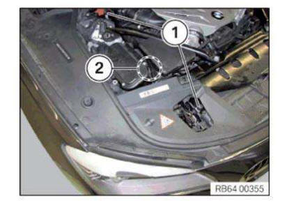
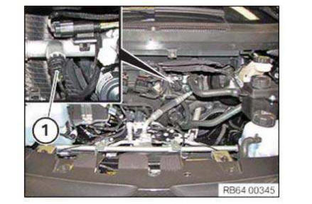
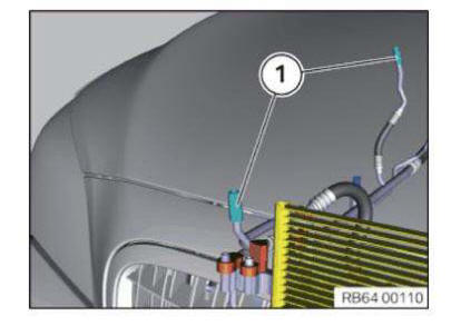
NOTE: On the F01, F02, F10, F11, an additional refrigerant low pressure connection (2) may be installed specific to the engine and model year.
This refrigerant low pressure connection (2) is not to be used in the inspection! Use exclusively refrigerant connections (1) for drawing off, evacuating and filling!
IMPORTANT: Risk of damage! Carefully move the climate service station! Comply with the operating instructions and service interval for the A/C service station! Make sure that the hoses of the A/C service station are drained after the drawing off or filling procedure! The climate service station contains highly sensitive components, such as scales. These components will be damaged due to improper handling, such as fast driving over a bump. This will result in a significant reduction of the measuring accuracy when drawing off and filling.
IMPORTANT: The vehicle must be parked on the floor during all drawing off, evacuation and filling procedures! Filling a raised vehicle will result in insufficient filling levels.
NOTE: In the event of complaints, perform A/C performance test!
If the system fails the test, draw off, evacuate and fill the heating and air conditioning system in accordance with the operating instructions of the relevant service station.
Instructions for drawing off air conditioning:
To help separation of refrigerant and refrigerant oil, run engine at low speed (800-1200 rpm) and with air conditioning turned on for a few minutes.
The limits the entrainment of refrigerant oil while it is drawn off.
Drawn-off refrigerant oil must be changed and reintroduced via the A/C service station.
During drawing off, set blower of heating and air-conditioning unit to middle blower speed. This ensures that drawing off is more effective since the pressure on the low pressure side increases.
Recycling: Dispose of drawn-off refrigerant oil as hazardous waste.
Observe country-specific waste disposal regulations.
Instructions for evacuating off air conditioning:
Before each filling, evacuate the refrigerant system.
Observe an evacuation time of at least 30 minutes.
The evacuation procedure removes all traces of ambient air, water vapor and any other gases present from the heating and air conditioning system. This enables subsequent system filling with refrigerant.
If the vacuum does not remain stable when the system is off, run the procedure for leaks in the refrigerant circuit.
During evacuation, set blower of heating and air-conditioning unit to middle blower speed. This ensures that evacuation is more effective since the pressure on the low pressure side increases.
Notes for filling heating and air conditioning system:
Before filling with refrigerant, replace the refrigerant oil entrained during drawing off.
Also top up any lost fluid as indicated in the table:
Loss of R134a refrigerant
Table 1 indicates the permitted loss of refrigerant after a specific period of time. There is no leak. refrigerant oil may not be topped up.
Table 2 indicates the amount of refrigerant oil must be topped up with an unapproved loss of refrigerant due to a leak after a specific period of time.
Different cases:
a. Loss of refrigerant per Table 1 is not exceeded
- Top up lost R134a refrigerant
- It is not permitted to top up the refrigerant oil
b. Loss of refrigerant per Table 1 is exceeded c. Top up lost R134a refrigerant d. refrigerant oil must be topped up additionally per Table 2
Follow NOTES FOR OPENING AND REPLACING PARTS in refrigerant circuit.
Depending on the type of component replaced on the heating and air conditioning system, it may be necessary to the top up the refrigerant oil, even if no measurable losses have occurred during drawing off. Follow the notes provided by the heating and air conditioning system manufacturer, taking account of the tolerances (and inaccuracies) indicated in the operating instructions of the relevant service station.
Information on the required refrigerant capacity of the air conditioning is found on the type plate (1).
If necessary, refer to the Technical Data for CAPACITY .
Installation note:
Reseal refrigerant filler necks on vehicle with sealing caps.
Leak detection with forming gas
NOTE: Leak detection with forming gas replaces the leak detection that is restricted in EU countries using UV.
Observe national regulations in all other countries!
IMPORTANT: Compliance with the manufacturers operating instructions provided in the equipment case is absolutely mandatory! Read and comply with the manufacturers operating instructions provided with the special tool particularly with regard to accident prevention, health protection and environmental protection.
Only the basic procedure is described in the following!
IMPORTANT: Wear personal protective clothing/equipment!
NOTE: Determine the customer's use behavior prior to leak detection!
Necessary preliminary work:
-
If components of the refrigerant circuit are contaminated, clean the engine compartment.
Otherwise, the sensor head of the leak detector will become contaminated.
COMPLY WITH NOTES AND INSTRUCTIONS ON HANDLING HIGH PRESSURE CLEANER .
- DRAIN OFF AIR CONDITIONING SYSTEM
- Fill the air conditioning system with forming gas
- Set pressure to 5 bar
To reach the components of the refrigerant circuit with leak detector, specific parts must be removed
depending on the vehicle.
Remove the following parts first immediately before the check of the respective components
- Drive belt from air conditioning compressor
- Center fresh air grille
- Covers
- Trim panels
- Air duct
- Intake silencer
- Bulkheads
- Parts of the interior equipment (automatic rear air-conditioning system)
With some vehicles, the air flaps of the automatic air flap control (LKS) must be opened.
F01 h, F02 h, F02, F03, F04:
Before filling the refrigerant circuit with forming gas, perform test module "Draining/Filling of refrigerant circuit".
Vehicle-specific notesI01:
Equipment specification with and without heat pump: To access the connections for the refrigerant lines, remove front luggage compartment well.
Equipment specification with heat pump:
Carry out the following steps before filling the refrigerant circuit with forming gas:
1. Switch on terminal 15: To do so, press the Start/Stop button without operating the brake pedal .
2. Switch off blower at IHKA controls (so that air conditioning compressor cannot start up).
3. Switch on low-beam headlight (so that terminal 15 can switch off automatically after a certain period).
If nec., charge the high-voltage battery (12 V battery is charged via the high-voltage battery).
4. Pull off connector (1).
This state must last for the duration of the entire leak detection process!
Equipment specification with and without heat pump:
After filling the refrigerant circuit with refrigerant, delete fault memory!
IMPORTANT: Always perform the leak detection with a pressure of 5 bar at first!
This is absolutely necessary to find certain leaks, such as in the area of the O-rings.
If no leak is detected, repeat the leak detection with 10 bar .
IMPORTANT: The leak detection may not be performed more than 3 h after filling the refrigerant circuit with forming gas!
Forming gas consists of 95% nitrogen and 5% hydrogen. The leak detector will detect hydrogen. If this is leaking from the refrigerant circuit even though the pressure remains, the leak detection bears no results.
IMPORTANT: Risk of damage! Maximum approved pressure: 10 bar .
Do not start the engine during the entire procedure!
Notes for handling the leak detector:
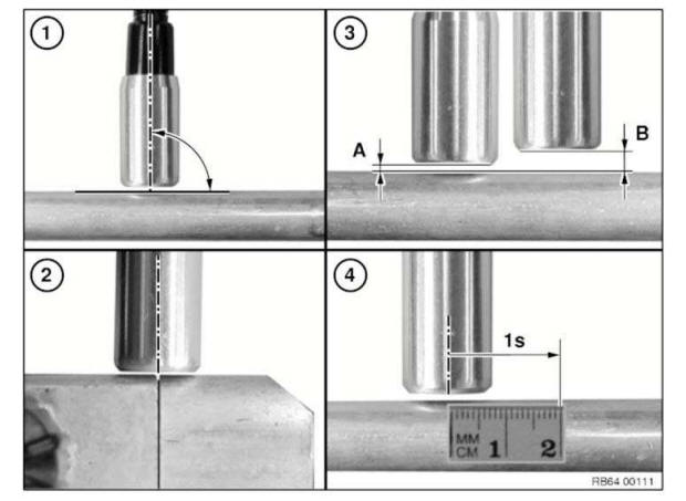
1. Sensor head should always stand vertical to the surface to be checked.
2. Sensor head must always be aligned to the center of the point to be checked. Slowly guide the sensor head around the point (e.g. connection point, sealing surface, etc.).
3. The optimal distance (A) between sensor head and surface to be checked should permanently be approximately 1 mm.
Maximum distance (B) at points that are difficult to access approximately 5 mm.
4. Checking speed may not be more than maximum 2 cm per s.
NOTE: If the leak detector displays a leak, remove the sensor head from the leak for approximately 10 s.
Then check if the leak is still displayed at the same point. Repeat the process up to three times, to ensure that a leak is actually present at this point.
NOTE: Replace the leaking component. Relieve the pressure from the refrigerant circuit prior to replacement.
IMPORTANT: Compliance with the instructions above is absolutely mandatory! Non-compliance will significantly reduce the efficiency of leak detection!
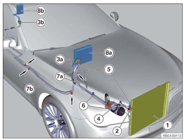
NOTE: The graphic shows the example of the refrigerant circuit on the F02 with the automatic rear air-conditioning system optional equipment.
Refrigerant circuits on other vehicles may differ from the graphic.
Refrigerant circuits of BMW i vehicles differ a lot from the figure
Overview components refrigerant circuit I01
Overview components refrigerant circuit I12
Pay attention to leak detection in these vehicles
Overview of positions to be checked:
- Air conditioning condenser
- Connection point between air conditioning condenser and refrigerant line
- Expansion valve, front (vehicles with and without automatic rear air-conditioning system)
- Expansion valve, rear (vehicles with automatic rear air-conditioning system)
- Air conditioning compressor
- Filler neck high pressure and low pressure
- Refrigerant pressure sensor
- Refrigerant line, front (vehicles with and without automatic rear air-conditioning system)
- Refrigerant line, rear (vehicles with automatic rear air-conditioning system)
- Evaporator, front (vehicles with and without automatic rear air-conditioning system)
- Evaporator, rear (vehicles with automatic rear air-conditioning system)
NOTE: Refrigerant line connection points are identified by arrows.
Checking sequence:
1. Check of components 1, 2, 3a, 4, 5, 6, 7a and 8a of the automatic front air-conditioning system.
If no fault found:
2. Check of components 3b, 7b, 8b and connection points of the automatic rear air-conditioning system.
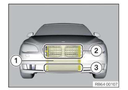
1. Air conditioning condenser:
Damage caused by stone chipping, etc. is the most frequent cause of air conditioning condenser leaks (1):
- Visual inspection in the area of the radiator grille (2) and air inlet grille, center (3).
- Check damaged points first.
- Check the remainder of the air conditioning condenser.
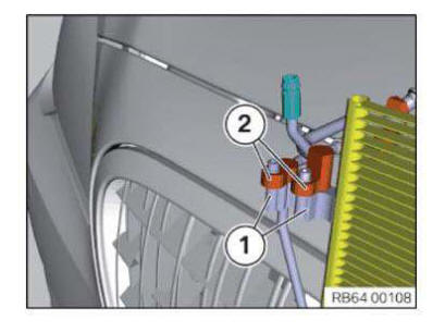
2. Connection point capacitor - refrigerant line
Check the connection point between the connection at the air conditioning condenser (1) and refrigerant lines (2).
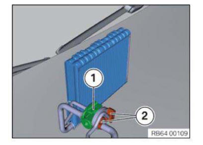
3. Expansion valve:
Check the connection point between the expansion valve (1) and refrigerant lines (2).
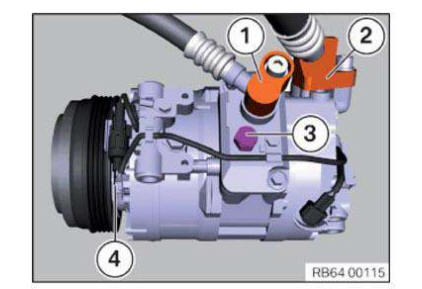
4. A/C compressor:
Remove drive belt from air conditioning compressor.
Check the following components on the air conditioning compressor:
- High-pressure connection
- Low pressure connection
- Pressure relief valve
- Radial shaft seal of the magnetic coupling: Turn the magnetic coupling several times by hand during the leak detection.
5. Filler neck
Blow out the fuel filler neck (1) prior to checking.
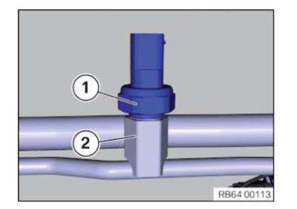
6. Refrigerant pressure sensor
Check the sealing surface between the refrigerant pressure sensor (1) and the refrigerant line (2).
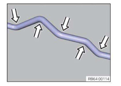
7. Refrigerant lines:
- Perform visual inspection
- Check damaged points first.
- Check bending points at points marked with an arrow. Leaks occur especially frequently at these points.
- Check the remainder of the refrigerant line.
8. Evaporator:
Remove the center fresh air grille.
Compliance with the following settings is absolutely required:
- Air recirculation function On
- Lowest blower speed
- Lowest temperature
- Set the air distribution to ventilation (air may only flow out of the center fresh air grille)
Position sensor head (1) in air duct of middle fresh air grille (2) as illustrated and move slowly from inside to outside above and below air flap (3). Carry out this operation on the left and right fresh air grilles.
IMPORTANT: Some vehicles have an expansion valve directly next to the fresh air intake for the passenger compartment.
In this case the expansion valve must be covered!
Following the completed leak detection:
- EVACUATE AND FILL HEATING AND AIR CONDITIONING SYSTEM
Leak detection with ultraviolet additives (uv additives) (bmw leak- testing case)
IMPORTANT: In EU countries, only limited UV leak detection is permitted! Observe national regulations in all other countries!
IMPORTANT: It is absolutely essential to read and comply with the equipment manufacturers operating instructions use provided in the equipment case! Read and comply with the manufacturers operating instructions provided with the special tool particularly with regard to accident prevention, health protection and environmental protection.
Use only BMW-approved UV additives (e.g. TRACER). Only the basic procedure is described in the following!
IMPORTANT: UV additives may not be used in vehicles with electric A/C compressors!
WARNING: Avoid contact with refrigerant.
Follow safety precautions when handling refrigerant .
IMPORTANT: Ultraviolet lamp gets very hot in the radiation area! Do not use the ultraviolet lamp without the filter glass.
Eyes and skin will suffer damage if the ultraviolet lamp is used without the filter glass.
When using the ultraviolet lamp, wear the safety goggles provided in the case.
NOTE:
- Fill the hose system of the hand pump completely with UV additive PRIOR to use
- The UV additive may be used exclusively for BMW-approved refrigerant oils
- Do not operate the air conditioning system while the hand pump is connected or in use
- The air conditioning system must always be filled with an adequate amount of refrigerant to enable the leak-detecting agent to be properly distributed
Necessary preliminary tasks:
Before actually testing for leaks, check the entire refrigerant circuit using the UV leak detection lamp to ensure that no UV additive is already in the area of the refrigerant circuit.
Leak areas which have already been detected by UV light must carefully cleaned with the cleaning agent provided in the case.
On initial use: Connect hand pump (1) to additive cartridge (2) and hose piece (3).
On initial use:
Attach vent valve (1) to quick-release coupling (2).
Turn handle (3) on hand pump to advance the piston until a small amount of UV additive emerges. This vents the hose system.
IMPORTANT: The entire hand pump with hose system must not be disassembled again once the filling work has been completed.
Attach quick-release coupling (1) to low-pressure connection (2) of air conditioning system.
Turn handle on hand pump (3) until the required amount of UV additive is added.
The quantity of UV additive to be added is dependent on the AMOUNT OF REFRIGERANT IN THE REFRIGERANT CIRCUIT :
- Air conditioning systems with refrigerant filling up to 900 g: one graduation mark (4) on additive cartridge
- Air conditioning systems with refrigerant filling in excess of 900 g: two graduation marks (4) on additive cartridge
NOTE: After filling, remove quick-release coupling (1) and if necessary use the cleaning agent contained in the special tool case to clean up the UV additive.
Further tasks:
- Start engine
- Run air conditioning system at highest stage for 5 - 10 minutes in order to ensure adequate distribution of dye in the system
- Turn off engine.
- Check all air conditioning system components for possible leaks
- Possible leakage is lit up green when the UV leak-detecting lamp and UV-absorbing safety goggles are used
Complete accompanying information label (1) with the relevant data and attach in an easily visible position next to the filling capacity information label (2).
Note for handling r134a refrigerant
Work on the refrigerant circuit may only be carried out by experts! Avoid all contact with liquid or gaseous R134a. Wear safety goggles and gloves when working on the refrigerant circuit.
- FOLLOW SAFETY INFORMATION FOR HANDLING R134A REFRIGERANT.
WARNING: Although R134a at normal temperature is non-toxic, not inflammable and not explosive in air in any mixture ratio, it is still essential to follow various safety precautions.
As a gas, R134a is colorless, odorless and heavier than air. If it enters the atmosphere, this may result in an imperceptible danger of asphyxiation or in cardiac palpitations, especially in workshop pits. Ventilate rooms adequately; if necessary, turn on installed extractor systems.
Store charged refrigerant pressure flasks in a place where they are not exposed to direct sunlight or any other heat source (max. 45 ºC). Also avoid exposing them to mechanical stress (e.g. by dropping).
Do not weld or solder on to filled heating and air conditioning systems or in rooms into which R134a may have escaped. Exposure to flames or high temperatures (≥ 50 ºC) may give rise to toxic decomposition products (fluorine gas). For this reason, do not smoke either.
In the event of fire, carbon dioxide (CO2 ), extinguishing powder and a sprayed water jet are deemed to be suitable extinguishant. Cool reservoirs at risk with a sprayed water jet (risk of bursting!).
If the protective caps on the filling valves are difficult to open, there is a risk of injury from leaking valve inserts (high pressure).
The filled refrigerant circuit of the A/C system is subject to excess pressure. Before carrying out repairs on the A/C system, it is absolutely essential to draw off the refrigerant.
- Before conducting repairs, check the actual pressure drop on the pressure gauge of the A/C service station.
R134a must be drawn off, cleaned and returned to the heating and air conditioning system using an A/C service station following the relevant operating instructions.
For a properly functioning A/C system, it is essential to have the greatest possible levels of cleanliness when working on the A/C system and the longest possible evacuation (at least 30 minutes dehumidification from refrigerant circuit) before each filling of the A/C system.
R134a absorbs very small amounts of moisture. Therefore, seal off opened pipes, condenser, evaporator, compressor and dryer flask immediately with plugs.
- If an A/C system has been completely drained by leakage, accident or repair, the DESICCANT INSERT must be replaced as excessive moisture may have entered the system.
With exchange parts, the plugs may only be removed immediately before the lines are connected. In the event of warranty claims, the used parts must be provided with plugs to be able to determine the cause of the damage.
Installation note: After each refill of an A/C system, check that the protective caps of the filler valves are hand-tight. They serve as additional seals.
Safety informations for handling refrigerant oil
WARNING: Danger of injury! Refrigerant circuit is under high pressure! Work on the refrigerant circuit may only be carried out by experts! Draw off refrigerant without fail BEFORE all repair work on the refrigerant circuit.
The refrigerant circuit is depressurized AFTER drawing off!
- Before conducting repairs, check the actual pressure drop on the pressure gauge of the A/C service station
Read and comply with the relevant operating instructions for the A/C service station used!
Protective measures/rules of conduct:
- Wear safety goggles
- Wear oil-resistant protective gloves
- Do not smoke!
- Observe country-specific safety regulations.
First aid measures:
- If swallowed: Do NOT induce vomiting, unless expressly instructed to do so by medical personnel. Do not administer anything to an unconscious person through their mouth. Consult a doctor immediately if larger quantities of this substance are swallowed. Loosen tight-fitting items of clothing (e.g. collar, tie, belt or similar).
- Eye contact: Remove contact lenses if worn. In the event of eye contact, rinse eyes for at least 15 minutes with plenty of water. It is essential to use WARM WATER. Consult a doctor.
-
Skin contact: In the event of skin contact, rinse immediately with plenty of water. Remove contaminated
clothes and shoes. Wash affected clothes before wearing again. Clean shoes thoroughly before reusing.
Call for a doctor .
- After inhalation: If inhaled, take the person affected outside into fresh air immediately and keep them under supervision. Call for a doctor. If breathing difficulties are experienced, administer additional oxygen. If the person affected stops breathing, administer the kiss of life.
IMPORTANT: Refrigerant is hygroscopic and must therefore be stored in suitable containers that are sealed airtight! refrigerant oil is non-combustible and non-explosive at normal temperatures. Nevertheless, the following points must be observed:
- Do not store in the vicinity of flames, heat sources or strongly oxidizing materials
- Suitable extinguishants are carbon dioxide (CO2 ) dry extinguishant and foam
Recycling
Catch and dispose of emerging refrigerant oil.
Observe country-specific waste disposal regulations.
Absorb escaping refrigerant oil with fluid-binding material.
Notify the relevant authorities if larger amounts of refrigerant are discharged into aboveground water supplies, drainage systems or subsoil.
Safety informations for handling tetrafluorethane refrigerant r134a
WARNING: Danger of injury! Refrigerant circuit is under high pressure! Work on the refrigerant circuit may only be carried out by experts! Draw off refrigerant without fail BEFORE all repair work on the refrigerant circuit.
The refrigerant circuit is depressurized AFTER drawing off.
- The pressure gauge on the A/C service unit must be checked for the actual pressure drop prior to repair work.
It is absolutely essential to read and observe the relevant operating instructions for the A/C service unit used!
Protective measures/rules of conduct:
- Wear safety goggles
- Wear oil-resistant protective gloves
- Do not smoke!
- Observe country-specific safety regulations.
First aid measures:
- Eye contact: In the event of contact with the eyes, rinse immediately with plenty of running water and consult an ophthalmologist.
- Skin contact: In the event of contact with skin, remove affected clothing immediately and rinse with plenty of water.
- After inhalation: If refrigerant vapors are inhaled in greater concentrations, remove the person affected to an area of fresh air and keep them under supervision. Call for a doctor. If breathing problems are experienced, breathe additional oxygen. If the person affected is breathing with difficulty or has stopped breathing, incline the person's head at the neck and administer the kiss of life.
 Microfilter
...

Other materials:
BMW X3 (F25) Service & Repair Manual > Brakes: Accelerator pedal actuation
REMOVING AND INSTALLING OR REPLACING ACCELERATOR PEDAL MODULE
Take off cap.
Release screw.
Pull accelerator pedal module upwards out of fixture.
Pull off connector (1).
Remove accelerator pedal module.
IMPORTANT:
Accelerator pedal module can only be replaced completely with ...
