BMW X3 (F25) Service & Repair Manual: Spring strut
- Information on replacing shock absorbers
- Removing and installing complete left or right spring strut shock absorber
- Removing and installing/replacing trailing link on left or right spring strut dome
- Replacing front left or right spring strut (edc)
- Replacing front left or right spring strut shock absorber
Information on replacing shock absorbers
Situation: When a shock absorber is faulty on one side (leaking, noises, etc.), often both shock absorbers on the axle in question are replaced.
Effect: This is not necessary for technical reasons and causes the manufacturer not to recognize the unnecessarily removed shock absorbers as defective parts. Unnecessarily high costs for the customer can be avoided by replacing the shock absorber on one side only.
Procedure: If one shock absorber is damaged, it is only necessary to replace both shock absorbers when the car has driven in excess of 80 000 km.
Exception: On all M-GmbH models, when a limit value is exceeded on one side, it is still necessary always to replace both shock absorbers on the relevant axle.
Removing and installing complete left or right spring strut shock absorber
Special tools required:
- 31 2 230
Installation note:
1. All screws, nuts, bolts and hose clamps removed during the repair must be replaced.
2. Retaining elements on chassis and suspension and steering parts must be replaced.
Necessary preliminary tasks:
- Detach OUTPUT SHAFT from wheel bearing and tie up.
- Remove BRAKE CALIPER and tie back.
- Remove BRAKE DISC .
- Remove ANTI-ROLL BAR LINK FROM SPRING STRUT.
- Remove TRACK ROD END FROM SWIVEL BEARING .
- Detach TRAILING LINK from swivel bearing.
- Remove WISHBONE.
- Detach WHEEL SPEED SENSOR from swivel bearing and unclip line from spring strut.
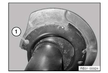
IMPORTANT: Risk of damage! When the output shaft is removed from the wheel bearing, the tripod (2) can be pulled out of the joint housing (1) and fall into the rubber gaiter (3). In this event, it will be necessary to install a new output shaft because the tripod (2) can jam or a roller of the tripod (2) can slip off the moulding. The roller would then be located in the gaiter (3) or bellows and result in rapid failure.
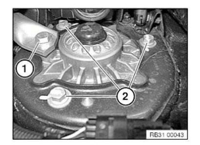
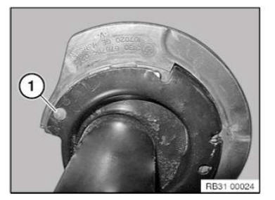
Secure spring strut against falling out.
Release screw (1) on strut.
Unfasten screws (2).
Installation note:
Replace screws.
For support bearings that have already been installed, do not use self-tapping screws.
If thread in support bearing is damaged, use Helicoil thread insert.
Remove spring strut with swivel bearing downwards out of wheel arch.
After installation:
- Perform CHASSIS/WHEEL ALIGNMENT CHECK .
Removing and installing complete left or right spring strut shock absorber
Special tools required:
- 31 2 230
Installation note:
1. All screws, nuts, bolts and hose clamps removed during the repair must be replaced.
2. Retaining elements on chassis and suspension and steering parts must be replaced.
Necessary preliminary tasks:
- Remove BRAKE CALIPER and tie back.
- Remove BRAKE DISC .
- Remove ANTI-ROLL BAR LINK FROM SPRING STRUT.
- Remove TRACK ROD END FROM SWIVEL BEARING .
- Detach TRAILING LINK from swivel bearing.
- Remove WISHBONE.
- Detach WHEEL SPEED SENSOR from swivel bearing and unclip line from spring strut.
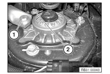
Secure spring strut against falling out.
Release screw (1) on strut.
Unfasten screws (2).
Installation note:
Replace screws.
For support bearings that have already been installed, do not use self-tapping screws.
If thread in support bearing is damaged, use Helicoil thread insert.
Remove spring strut with swivel bearing downwards out of wheel arch.
After installation:
- Carry out wheel alignment procedure
Removing and installing/replacing trailing link on left or right spring strut dome
Special tools required:
- 00 9 120
IMPORTANT: Vehicles must not be driven without tension struts.
Driving without trailing links may damage the vehicle body.
trailing links can be secured with screws or nuts.
Screws must be tightened to specified torque and then tightened down to specified angle of rotation with special tool 00 9 120 .
Necessary preliminary tasks:
- Remove COWL PANEL COVER .
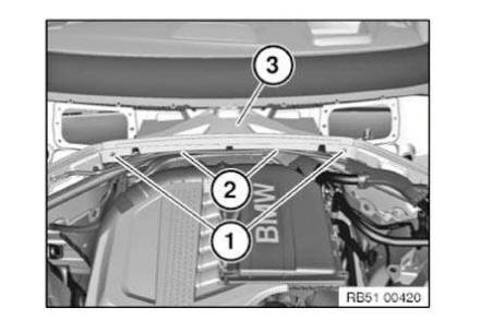
Release screws (1).
Lever out cable clip (2).
Remove cover (3).
Unfasten cable clip (3).
Release screws (1).
Remove trailing link (2).
Installation note: Replace screws (1), tighten to specified torque and then to angle of rotation.
Replacing front left or right spring strut (edc)
Special tools required:
- 31 3 340
- 31 3 341
- 31 3 355
- 33 0 040
- 31 0 040
WARNING: Prior to each use of special tool 31 3 340 , it is essential to read the associated operating instructions fully! All the safety precautions and instructions contained in the Owner's Handbook must be strictly observed! Failure to observe these safety precautions and instructions increases the risk of serious physical injury, damage to your health and damage to property and equipment!
IMPORTANT:
- Prior to each use, check the special tools for defects, modifications and operational reliability.
- Damaged/modified special tools must not be used!
- No changes or modifications may be made to the special tools!
- These special tools are intended solely for the purpose of tightening and relieving cylindrical and tapered suspension springs.
- Keep special tools dry, clean and (down to the spindle) free from grease.
- Impact screwdrivers are prohibited! Risk of damage inside the shock absorber!
- Do not compress coil spring to full extent.
Necessary preliminary tasks:
Necessary preliminary tasks:
- Remove FRONT SPRING STRUT .
Removing:
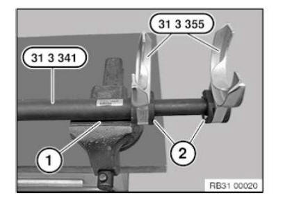
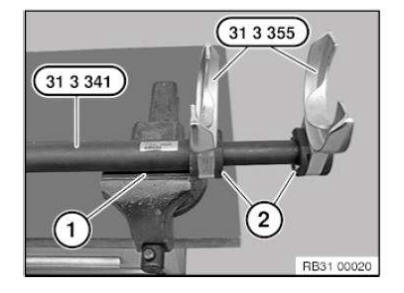
Clamp special tool 31 3 341 with guide (1) in vice.
Fit special tools 31 3 355 from above on special tool 31 3 341 until retaining bolts (2) can be felt and heard to snap into place.
Check seating of special tools 31 3 355 and, if necessary, correct.
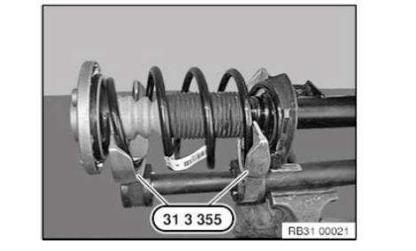
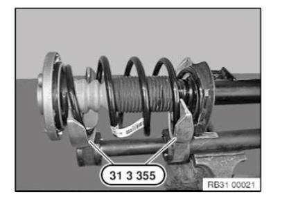
Clean coil spring to remove all coarse dirt and mount on special tools 31 3 355 .
WARNING: Coils of coil spring must be located completely in recesses of special tools 31 3 355!
Tension coil spring with special tool 31 3 341 until stress on piston rod is relieved.
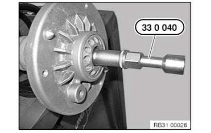
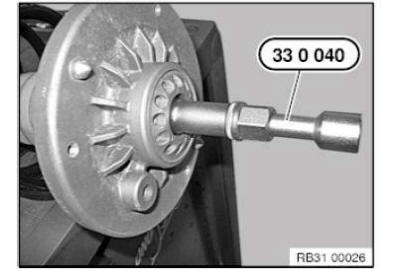
Take off cap.
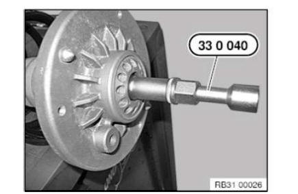
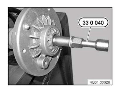
Release nut with special tool 33 0 040 (grip piston rod in the process).
Remove support bearing.
Remove shock absorber with auxiliary damper, gaiter and lower spring pad from tensioned coil spring.
Installation note: When renewing support bearing: Renew screws (self-tapping if necessary).
Impact screwdrivers are prohibited! Risk of damage inside the shock absorber! If necessary, remove auxiliary damper (1) with gaiter (2) and spring pad (3) from shock absorber.
Remove swivel bearing .
Installation note:
When renewing spring strut/swivel bearing, follow tightening specifications! Replace swivel bearing .
Check auxiliary damper (1), gaiter (2) and spring pad (3) for damage, replace if necessary.
Installation note: Align spring pad (3) with spring pad by way of recess (1).
IMPORTANT: Align lower end of coil spring (1) flush with spring pad (2) as shown.
Upper coil of coil spring must rest positively on spring cup!
Insert shock absorber in tensioned coil spring.
Relieve tension on coil spring.
Check installation position of gaiter, correct fold if necessary.
Check support bearing and spring pad for damage, replace if necessary.
Attach support bearing to piston rod.
Replace nut and tighten down with special tool 31 0 040 (grip piston rod in the process).
Fit cover cap.
Impact screwdrivers are prohibited! Risk of damage inside the shock absorber! After installation:
- Use the diagnosis system to perform the wheel speed accelerator sensor adjustment.
Replacing front left or right spring strut shock absorber
Special tools required:
- 31 3 340
- 31 3 341
- 31 3 355
- 33 0 040
- 31 0 040
WARNING: Prior to each use of special tool 31 3 340, it is essential to read the associated Owner's Handbook fully! All the safety precautions and instructions contained in the Owner's Handbook must be strictly observed! Failure to observe these safety precautions and instructions increases the risk of serious physical injury, damage to your health and damage to property and equipment!
IMPORTANT:
- Prior to each use, check the special tools for defects, modifications and operational reliability.
- Damaged/modified special tools must not be used!
- No changes or modifications may be made to the special tools!
- These special tools are intended solely for the purpose of tightening and relieving cylindrical and tapered suspension springs.
- Keep special tools dry, clean and (down to the spindle) free from grease.
- Impact screwdrivers are prohibited! Risk of damage inside the shock absorber!
- Do not compress coil spring to full extent.
Necessary preliminary tasks:
- Remove front spring strut
Removing: Clamp special tool 31 3 341 with guide (1) in vice.
Fit special tools 31 3 355 from above on special tool 31 3 341 until retaining bolts (2) can be felt and heard to snap into place.
Check seating of special tools 31 3 355 and, if necessary, correct.
Clean coil spring to remove all coarse dirt and mount on special tools 31 3 355.
WARNING: Coils of coil spring must be located completely in recesses of special tools 31 3 355!
Tension coil spring with special tool 31 3 341 until stress on piston rod is relieved.
Take off cap.
Release nut with special tool 33 0 040 (grip piston rod in the process).
Remove support bearing.
Remove shock absorber with auxiliary damper, gaiter and lower spring pad from tensioned coil spring.
Installation note:
When renewing support bearing: Renew screws (self-tapping if necessary).
Impact screwdrivers are prohibited! Risk of damage inside the shock absorber! If necessary, remove auxiliary damper (1) with gaiter (2) and spring pad (3) from shock absorber.
Relieve tension on coil spring and remove from special tools 31 3 355.
Remove swivel bearing .
Installation note: When renewing spring strut/swivel bearing, follow tightening specifications!
Assembly:
Accommodate coil spring with special tools 31 3 355.
Twist coil spring until lower end of coil spring (1) is flush with end (2) of special tool 31 3 355.
WARNING: Do not compress coil spring to full extent.
Coils of coil spring must be located completely in recesses of special tools 31 3 355!
Tension coil spring.
Check auxiliary damper (1), gaiter (2) and spring pad (3) for damage, replace if necessary.
NOTE: Align spring pad (3) with spring pad by way of recess (1).
IMPORTANT: Align lower end of coil spring (1) flush with spring pad (2) as shown.
Upper coil of coil spring must rest positively on spring cup!
Insert shock absorber in tensioned coil spring.
Relieve tension on coil spring.
Check installation position of gaiter, correct fold if necessary.
Check support bearing and spring pad for damage, replace if necessary.
Attach support bearing to piston rod.
Replace nut and tighten down with special tool 31 0 040 (grip piston rod in the process).
Fit cover cap.
Impact screwdrivers are prohibited! Risk of damage inside the shock absorber!

 Spring with suspension
MEASURING VEHICLE RIDE HEIGHT
Determine actual ride height (A) - to do so, attach tape measure to rim flange (2) at bottom middle and measure
to w ...
Other materials:
BMW X3 (F25) Service & Repair Manual > Driveline+Axles: Final drive oil for bmw m1 motorsport coupe
3.0 FINAL DRIVE OIL FOR BMW M1 MOTORSPORT COUPE
The final drive of a BMW M1 is integrated into the manual transmission and the oil supply is accomplished
with a mutual oil filling.
Use reputable brand SAE 80 manual transmission oil conforming with specifications MIL-L-2105 A or API-
GL 4.
4 ...
