BMW X3 (F25) Service & Repair Manual: Rear axle
- Adapter
- Basic body
- Bush
- Device
- Extension
- Fixture
- Frame
- Holder
- Holding sleeve
- Insert
- Mandrel
- Nut
- Plate
- Pliers
- Ring
- Rod
- Screw
- Shaped element
- Shaped part
- Shell
- Socket wrench
- Spindle
- Spring cups
- Spring tensioner
- Synchronising key
- Tool
- Washer
- Wrench
Adapter
Adapter AM
NOTE: Adapter M4 (Ø 96mm) in connection with adapter kit 2 (BMW), (81642155746), for removal and installation of wheel bearings, propeller shafts and drive flanges.
SI number
08 06 09 (544)
Adapter AM
NOTE: Adapter R7 (M24/Ø 87/95mm) in connection with adapter kit F03 (81 64 2 348 804) for installation and removal of wheel bearings, propeller shafts and drive shafts.
SI number
08 02 13 (900)
Adapter AM
NOTE: Adapter P5 (/Ø 45/82.5mm) in connection with wheel bearing adapter kit F30 (84mm, no longer in Catalogue) for installation and removal of wheel bearings, propeller shafts and drive shafts.
SI number
08 09 12 (873)
Adapter AM
NOTE: Adapter N1 (Ø 49mm) in connection with adapter kit 2 (BMW), (81 64 2 155 746), for removal and installation of wheel bearings, propeller shafts and drive flanges.
SI number
08 06 09 (544)
Adapter AM
NOTE: Adapter R6 (M24/Ø 63/75mm) in connection with adapter kit F30 (84mm wheel bearings) for installation and removal of wheel bearings, propeller shafts and drive shafts.
SI number
08 09 12 (873)
Adapter AM
NOTE: Adapter N4 (Ø 39mm) in connection with adapter kit 2 (BMW), (81 64 2 155 746), for removal and installation of wheel bearings, propeller shafts and drive flanges.
SI number
08 06 09 (544)
Adapter Mechanical tool
NOTE: For installing the rear axle shaft
Storage Location
X4
Adapter Mechanical tool
NOTE: For installing the rear axle shaft
Storage Location
X4
Adapter AM
NOTE: Adapter M2 (Ø 88mm) in connection with adapter kit 2 (BMW), (81 64 2 155 746), for removal and installation of wheel bearings, propeller shafts and drive flanges.
SI number
08 06 09 (544)
Adapter AM
NOTE: Adapter M8 for removal and installation of wheel bearings, propeller shafts and drive flanges.
SI number
08 06 09 (544)
Adapter AM
NOTE: Adapter P3 (Ø 39/72mm) in connection with adapter kit 2 (BMW), (81 64 2 155 746), for removal and installation of wheel bearings, propeller shafts and drive flanges.
SI number
08 06 09 (544)
Adapter AM
NOTE: Adapter R3 (M24/Ø 69/79mm) in connection with adapter kit 2 (BMW), (81 64 2 155 746), for removal and installation of wheel bearings, propeller shafts and drive flanges.
SI number
08 06 09 (544)
Adapter AM
NOTE: Adapter R8 (M24/Ø 74/83mm) in connection with adapter kit F03 (81642348804) for installation and removal of wheel bearings, propeller shafts and drive shafts.
SI number
08 02 13 (900)
Adapter AM
NOTE: Adapter P6 (/Ø 51/89mm) in connection with adapter kit F03 (81 64 2 348 804) for installation and removal of wheel bearings, propeller shafts and drive shafts.
SI number
08 02 13 (900)
Adapter AM
NOTE: Adapter P1 (Ø 45/85mm) in connection with adapter kit 2 (BMW), (81 64 2 155 746), for removal and installation of wheel bearings, propeller shafts and drive flanges.
SI number
08 06 09 (544)
Adapter AM
NOTE: Adapter P4 (Ø 42/75 mm) in combination with adapter kit 2 BMW (81 64 2 155 746) for removing and installing wheel bearings, output shafts and drive flanges.
SI number
08 06 09 (544)
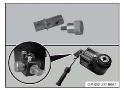
Adapter AM
NOTE: Adapter Z1 to attach torque wrench. Used in connection with hydraulic cylinder, (81642156246), for removal and installation of wheel bearings, propeller shafts and drive flanges.
SI number
08 04 12 (797)
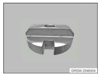
Adapter AM
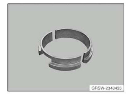
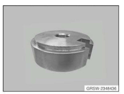
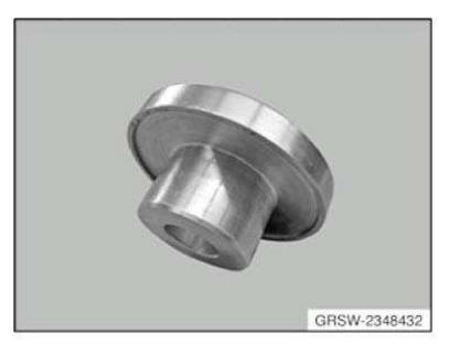
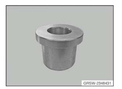
NOTE: Adapter set F03 as a supplement to the hydraulic tool for removal and installation of wheel bearings, output shafts and drive flanges.
SI number
08 02 13 (900)
Consisting of:
1 = 2348430
3 = 2348432
5 = 2348434
4 = 2348436
2 = 2348431
Adapter AM
NOTE: Adapter R4 (M24/Ø 64/75mm) in connection with adapter kit 2 (BMW), (81 64 2 155 746), for removal and installation of wheel bearings, propeller shafts and drive flanges.
SI number
08 06 09 (544)
Adapter AM
NOTE: Adapter R2 (M24 tapered) in connection with adapter kit 2 (BMW), (81 64 2 155 746), for removal and installation of wheel bearings, propeller shafts and drive flanges.
SI number
08 06 09 (544)
Adapter AM
NOTE: Adapter M6 (Ø 102/113mm) in connection with adapter kit 2 (BMW), (81 64 2 155 746), for removal and installation of wheel bearings, propeller shafts and drive flanges.
SI number
08 06 09 (544)
Adapter AM
NOTE: Adapter N5 (/Ø 51mm) in connection with adapter kit F03 (81642348804) for installation and removal of wheel bearings, propeller shafts and drive shafts.
SI number
08 02 13 (900)
Adapter AM
NOTE: Adapter H2 (tooth finder) in combination with adapter kit 1 BMW (81 64 2 155 745) for removal and installation of wheel bearings, output shafts and drive flanges.
SI number
08 06 09 (544)
Adapter AM
NOTE: Adapter N2 (Ø 45mm) in connection with adapter kit 2 (BMW), (81 64 2 155 746), for removal and installation of wheel bearings, propeller shafts and drive flanges.
SI number
08 06 09 (544)
Adapter AM
NOTE: Adapter P2 (Ø 49/90mm) in connection with adapter kit 2 (BMW) and adapter kit 3 RR for removal and installation of wheel bearings, propeller shafts and drive flanges.
SI number
08 06 09 (544)
Adapter AM
NOTE: Adapter B1 in connection with adapter kit 1 (BMW), (81 64 2 155 745) and MINI adapter kit (81 64 2 294 517), for removal and installation of wheel bearings, propeller shafts and drive flanges.
SI number
08 06 09 (544)
Adapter AM
NOTE: Adapter R5 (M24/Ø 59/70mm) in connection with adapter kit 2 (BMW), (81 64 2 155 746), for removal and installation of wheel bearings, propeller shafts and drive flanges.
SI number
08 06 09 (544)
Adapter AM
NOTE: (adapter with nut and washer)
Storage Location: Z3
Z4
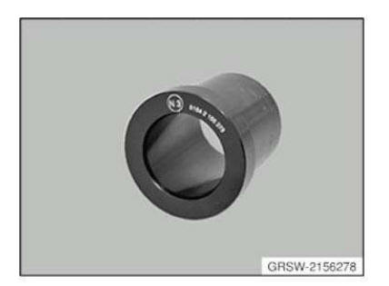
Adapter AM
NOTE: Adapter N3 (Ø 42mm) in connection with adapter kit 2 (BMW), (81 64 2 155 746), for removal and installation of wheel bearings, propeller shafts and drive flanges.
SI number
08 06 09 (544)
Adapter AM
NOTE: Adapter M5 (Ø 90mm) in connection with adapter kit 2 (BMW), (81 64 2 155 746), for removal and installation of wheel bearings, propeller shafts and drive flanges.
SI number
08 06 09 (544)
Adapter AM
NOTE: Adapter M1 (Ø 100/101mm) in connection with adapter kit 2 (BMW), (81 64 2 155 746), for removal and installation of wheel bearings, propeller shafts and drive flanges.
SI number
08 06 09 (544)
Adapter AM
NOTE: Adapter M3 (Ø 102mm) for installation and removal of wheel bearings, propeller shafts and drive shafts.
SI number
08 06 09 (544)
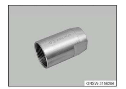
Adapter AM
NOTE: Adapter G3 (M27x1.5/M20) in connection with adapter kit 1 (BMW), (81 64 2 155 745), for removal and installation of wheel bearings, propeller shafts and drive flanges.
SI number
08 06 09 (544)
Adapter AM
NOTE: Adapter E2 (M24) in connection with adapter kit 1 (BMW), (81 64 2 155 745), for removal and installation of wheel bearings, propeller shafts and drive flanges.
SI number
08 06 09 (544)
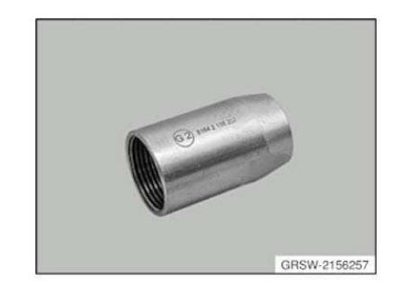
Adapter AM
NOTE: Adapter G2 (M24x1.5/M20) in connection with adapter kit 1 (BMW), (81 64 2 155 745), for removal and installation of wheel bearings, propeller shafts and drive flanges.
SI number
08 06 09 (544)
Adapter AM
NOTE: Adapter R1 (M24/Ø 77/82mm) in connection with adapter kit 2 (BMW), (81 64 2 155 746), for removal and installation of wheel bearings, propeller shafts and drive flanges.
SI number
08 06 09 (544)
Adapter AM
NOTE: Adapter G1 (M22x1.5/M20) in connection with adapter kit 1 (BMW), (81 64 2 155 745), for removal and installation of wheel bearings, propeller shafts and drive flanges.
SI number
08 06 09 (544)
Basic body
Basic body AM
NOTE: No longer available separately, only available as part of complete tool set 0493416 = 33 4 400.
Basic body Minimum set: Mechanical tools AM
NOTE: Only available via complete tool set 33 5 120 -> (83 30 0 495 851).
SI number
01 22 06 (307)
BASIC UNIT
Basic unit AM
Replaced by: 83300492436
NOTE: Discontinuation and replaced by 33 4 200. (0 492 436)
BELT
Belt AM
NOTE: (Tensioning strap)
BRACE
Minimum set: Mechanical tools Brace AM
NOTE: Applies to: BMW i Aftersales Basic contour-graphic silhouette foil is included in the delivery specification.
Storage Location
B36
SI number
01 13 13 (968)
BRIDGE
Bridge AM
NOTE: (Support bridge)
Bush
Bush Mechanical tool
Replaced by: 83300492341
NOTE: (Impact bush) For radial seal on output flange - Replaced by 33 3 450. (0 492 341)
Bush AM
Replaced by: 83300493416
NOTE: (Clamping bush) Discontinuation and replaced by 33 4 400. (0 493 416)
Bush AM
NOTE: Series: E31, E46
Storage Location
C14
Bush AM
NOTE: For accommodating the trailing arm when pressing out
Storage Location
X5
Bush AM
NOTE: (Pressure bushing) For pressing the ball joint into the wishbone
Bush AM
NOTE: For accommodating the engine support arm or wheel carrier when pressing out the ball joint
Storage Location
X5
Bush AM
NOTE: (Pressure bushing) For pressing the ball joint out of the wishbone
Bush AM
NOTE: (Bush (for removal and installation)) Deletion, only available via tool set
Storage Location
C53
SI number
01 18 05 (214)
Bush AM
NOTE: For accommodating the leading link when pressing out
Storage Location
Z8
Bush Mechanical tool
NOTE: (Impact bush) For driving in the radial seal on the drive flange
Storage Location
X7
Bush AM
NOTE: For holding the wishbone when pressing out the rubber mount

Bush Mechanical tool
Replaced by: 83300492339
NOTE: (Impact bush) For fitting the radial sealing rings in the rear axle final drive on the drive flange - Replaced by 33 3 430. (0 492 339)
Bush Mechanical tool
Replaced by: 83300492340
NOTE: (Impact bush) For radial sealing ring on the drive flange without axial sealing lip (final drive type G) and for fitting the radial sealing ring of the camshaft (M40) - Replaced by 33 3 440. (0 492 340)
CASE
Case AM
NOTE: (Case) with label.
CASE
Case Minimum set: Mechanical tools AM
NOTE: (Case) Case with insert discontinued, can only be ordered using complete tool
SI number
01 22 06 (307)
CLIP
Clip Mechanical tool
NOTE: (Mounting bracket) For short neck rear axle differential - model year: from 79
Clip Mechanical tool
NOTE: (Mounting clip) For rear axle differential unit - model: 1800 - 2000CA, 2500 - 3.3L, 525, 3.0CS - 3.0CSi-L
CONNECTOR
Connector AM
NOTE: (Basic body) For transmissions S5D 260Z, S5D 310Z and S5D 320Z;Discontinued, only available via complete tool
Storage Location
Y4
Z4
Device
Device AM
NOTE: For determining the installation size of the bevel drive pinion in the rear axle final drive
Consisting of:
1. Holder
NOTE: (Dial gauge holder)
2. Washer
NOTE: (Measuring disc)
Device AM
NOTE: For determining the installation size of the bevel drive pinion in the rear axle final drive
Consisting of:
1. Holder
NOTE: (Dial gauge holder)
2. Washer
NOTE: (Measuring disc)
Device AM
NOTE: (Pulling device) For pulling out the rubber mount in the final drive
Storage Location
A14
B14
Consisting of:
1. Spindle
NOTE: (Threaded spindle, long) Series: E36/5 sale of existing inventory and then available as part of set of special tools 33 2 120 = 83 30 0 492 179 only - as of 09.12.2011
2. Nut
NOTE: Liquidation of existing inventory and then available only as a complete tool set 33 2 120 = 83 30 0 492 179 - as of 09.12.2011

3. Synchronising key
4. HolderNOTE: (Countersupport) 0496208 =119850
Device AM
NOTE: For determining the installation size of the bevel drive pinion in the rear axle final drive
Consisting of:
1. Holder
NOTE: (Dial gauge holder)
2. Washer
NOTE: (Measuring disc)
Device AM
NOTE: For removing and installing the rubber mount in the 20º trailing arm
Storage Location
B10
C10
Consisting of:
1. Nut
NOTE: (Nut with bearing) Model series: E28, E30, E83
2. Spindle
NOTE: Series: E28, E30, E83
3. Holding sleeve
NOTE: Series: E28, E30 discontinued, available as part of set of special tools only
4. Synchronising key
5. Synchronising key
NOTE: (Synchronising key) Model series: E28, E30 Model: 518 - 735i discontinued, available as part of set of special tools only
6. Synchronising key
NOTE: Series: E28, E30 Model: 316 - 323i discontinued, available as part of set of special tools only
Device AM
NOTE: For removing and installing the ball joint in the wishbone
SI number
01 01 89 (989)
Consisting of:
1. Shaped element
NOTE: For positioning when pressing out the ball joint
2. Bush
NOTE: (Pressure bushing) For pressing the ball joint out of the wishbone
3. Shaped element
NOTE: For positioning the wishbone when pressing in the ball joint
4. Bush
NOTE: (Pressure bushing) For pressing the ball joint into the wishbone
Device Mechanical tool
NOTE: (mounting fixture) For rear axle final drive with modified bore hole - Model: from 83
Device Mechanical tool
NOTE: (Device) For function check of the mechanical limited slip differential
Device AM
NOTE: For determining the side clearance of the differential side gears
Storage Location
Y4
Consisting of:
1. Washer
NOTE: (Washer with thread)
2. Washer
NOTE: (Washer without thread)
Device AM
NOTE: For removing and installing the rubber mount in the trailing arm
SI number
01 01 89 (989)
Consisting of:
1. Holding sleeve
NOTE: (support sleeve) During extraction
2. Holding sleeve
NOTE: (Press-out sleeve)
3. Holding sleeve
NOTE: (Press-in sleeve)
4. Shaped element
NOTE: For pressing in
Device AM
NOTE: For determining the installation size of the bevel drive pinion in the rear axle final drive
Consisting of:
1. Holder
NOTE: (Dial gauge holder)
2. Washer
NOTE: (Measuring disc)
Device AM
NOTE: For removing and installing ball joint in wheel carrier.
Storage Location
C53
SI number
01 18 05 (214)
Consisting of:
1. Synchronising key
NOTE: (Thrust piece (for removing)) Deletion, only available via tool set
2. Bush
NOTE: (Bush (for removal and installation)) Deletion, only available via tool set
3. Synchronising key
NOTE: (Thrust piece (for installing)) Deletion, only available via tool set
Device AM
NOTE: For determining the side clearance of the differential side gears in the differential housing
Storage Location
Z3
Z4
Consisting of:
1. Holder
NOTE: (Dial gauge holder)
2. Adapter
NOTE: (adapter with nut and washer)
3. Extension
NOTE: (extension (2 x))
Device AM
NOTE: For determining the side clearance of the differential side gears
Storage Location
Y3
Consisting of:
1. Screw
2. Washer
Device AM
NOTE: For removing and installing the rubber mount in the wishbone
SI number
01 01 89 (989)
Consisting of:
1. Holding sleeve
NOTE: (Support sleeve) For pressing out
2. Holding sleeve
NOTE: (Press-out sleeve)
3. Holding sleeve
NOTE: (Press-in sleeve)
4. Shaped element
NOTE: For pressing in
Device Mechanical tool
NOTE: For determining the installation dimension of the drive bevel gear in the rear axle differential (also E36/3 and E36/7)
Device AM
NOTE: (Holding device) For fixing the final drive on the assembly stand
SI number
01 05 95 (932)
Consisting of:
1. Frame
NOTE: (Main frame)
2. Screw
NOTE: (Knurled screws (M16 2 x))
Device Mechanical tool
Replaced by: 83300494611
NOTE: For removing the rear axle final drive/Replaced by 33 4 420. (0 494 611)
SI number
01 10 90 (288)
Device AM
NOTE: For determining the installation size of the bevel drive pinion in the rear axle final drive
Consisting of:
1. Holder
NOTE: (Dial gauge holder)
2. Washer
NOTE: (Measuring disc)
Device AM
NOTE: For removing inner wheel bearing races on rear axle
SI number
08 12 14 (155)
Consisting of:
1. Basic body
NOTE: No longer available separately, only available as part of complete tool set 0493416 = 33 4 400.
2. Spindle
NOTE: No longer available separately, only available as part of complete tool set 0493416 = 33 4 400.
3. Wrench
NOTE: (Ignition key) Discontinued, only available via complete tool
4. Wrench
NOTE: (Ignition key) Discontinued, only available via complete tool
5. Pliers
NOTE: (Clamping ring (45 to 51 mm)) No longer available separately, only available as part of complete tool set 0493416 = 33 4 400.
6. Pliers
NOTE: (Clamping ring (50 to 55 mm)) No longer available separately, only available as part of complete tool set 0493416 = 33 4 400.
7. Pliers
NOTE: (clamping ring (55...61 mm)) Model series: E67 No longer available separately, only via complete tool set 0493416 = 33 4 400.
8. Ring
NOTE: (Clamping ring) Model series: F01, F02. Available only as complete special tool set 33 4 400.
9. Synchronising key
NOTE: Series: F01, F02. Remaining inventories will be sold off and then it will no longer be available separately, only available as part of complete tool set 0493416 = 33 4 400.
Device Minimum set: Mechanical tools AM
NOTE: For removing rubber mount in rear axle support.
Storage Location
A8
B8
SI number
01 02 99 (417)
Consisting of:
1. Pipe
NOTE: (Threaded tube) Deletion, only available via tool set
2. Shaped part
NOTE: (Shaped part) 2 pieces Model series: E38, E39, E46 Deletion, only available via tool set
3. Shaped part
NOTE: (Shaped part)
4. Rod
NOTE: (Guide rod)
5. Rod
NOTE: (Guide rod) With thread dog point
6. Plate
NOTE: (Fixing plate) With screws Deletion, only available via tool set
7. Synchronising key
NOTE: (Synchronising key (2 x)) With screws - model series: E38, E39, E46 Deletion, only available via tool set
8. Shaped part
NOTE: (Shaped part) 2 pieces Model series: E39/2, E65, E67, RR1
9. Synchronising key
NOTE: (Synchronising key (2 x)) With countersunk screw - model series: E39/2, E65, E67, E87
Device Minimum set: Mechanical tools AM
NOTE: For removing and installing rubber mount in rear axle final drive at front.
Storage Location
A22
SI number
01 22 06 (307)
Consisting of:
1. Washer
NOTE: Discontinued, can only be ordered using complete tool
2. Holding sleeve
NOTE: Discontinued, can only be ordered using complete tool
3. Washer
NOTE: Discontinued, can only be ordered using complete tool
4. Holding sleeve
NOTE: Discontinued, can only be ordered using complete tool
5. Washer
NOTE: Discontinued, can only be ordered using complete tool
6. Nut
NOTE: (Nut M12x1.5) discontinued, can only be ordered using complete tool
Device AM
NOTE: For removing and installing the rubber mount in the support tube of the rear axle final drive mounting
SI number
01 01 89 (989)
Consisting of:
1. Plate
NOTE: (Shaped plate, top) For removing
2. Plate
NOTE: (Shaped plate, top) For pulling in
3. Plate
NOTE: (Shaped plate, bottom) For pulling in
Device Mechanical tool
Replaced by: 83300492079
NOTE: (Fixture) For all rear axle final drives - model year: From 88 - Replaced by 33 1 070. (0 492 079)
Device AM
NOTE: For pulling off drive flanges (also E46/16).
Storage Location
C17
C18
Consisting of:
3 = Washer
4 = Plate
NOTE: (adapter plate) Transmission: GS6-57DZ, GS6-53BZ (G transmission) GS6- 51DZ, GS6-51BZ (H transmission) Deletion, only available via tool set
5 = Screw
NOTE: (countersunk screws M10x30 (3 x)) Transmission: GS6-57DZ, GS6-53BZ (G transmission) GS6-51DZ, GS6-51BZ (H transmission) Deletion, only available via tool set
1 = Spindle
NOTE: Discontinued, can only be ordered using complete tool
2 = Mandrel
NOTE: Discontinued, can only be ordered using complete tool
Device AM
NOTE: Device A1 in connection with adapter kit 1 (BMW), (81 64 2 155 745), for removal and installation of wheel bearings, propeller shafts and drive flanges.
SI number
08 06 09 (544)
Device AM
NOTE: For removing and installing outer rings of taper roller bearings
Consisting of:
1 = Shaped part
NOTE: (Shaped part)
2 = Spindle
NOTE: (Spindle, short)
4 = Nut
5 = Washer
NOTE: (Installation washer (2 pieces))
6 = Bridge
NOTE: (Support bridge)
7 = Washer
NOTE: (Thrust washer)
8 = Holding sleeve
NOTE: (Pressure sleeve) Can no longer be ordered separately. Only available as part of set 11 5 330 = 83 30 0 495 127.
Device Minimum set: Mechanical tools AM
NOTE: For removing and installing output shaft in rear axle final drive.
Storage Location
A22
B22
C22
SI number
01 01 07 (333)
Consisting of:
1 = Basic body
NOTE: Only available via complete tool set 33 5 120 - > (83 30 0 495 851).
2 = Screw
NOTE: (Knurled screw with thrust piece) available as part of set of special tools 33 5 120 -> (83 30 0 495 851) only.
3 = Rod
NOTE: Only available via complete tool set 33 5 120 - > (83 30 0 495 851).
4 = Shaped element
NOTE: (Shaped element) shaped element (bearing shell) available as part of set of special tools 33 5 120 -> (83 30 0 495 851) only.
5 = Shaped element
NOTE: Sale of existing inventory then available as part of set of tools 33 5 120 -> (83 30 0 495 851) only.
7 = Shaped part
NOTE: For driving output shaft into rear axle final drive.
6 = Shaped part
NOTE: For pressing output shaft out of rear axle final drive.
In conjunction with: 33 5 120
Extension
Extension Minimum set: Mechanical tools AM
NOTE: (Extension (1 item)) discontinued, can only be ordered using complete tool
SI number
01 21 06 (300)
Extension Minimum set: Mechanical tools AM
NOTE: (2 pieces) Pull-out extension for 33 5 040, 33 5 050, 33 5 060.
Storage Location
A18
B18
SI number
01 21 06 (300)
Consisting of:
1. Extension
NOTE: (Extension (1 item)) discontinued, can only be ordered using complete tool
Extension AM
NOTE: (extension (2 x))
Storage Location
Z3
Extractor AM
NOTE: (Rillex extractor) For bevel pinion and differential case (rear diff)/for installation of camshaft sprocket on crankshaft (M70)/for removing bearing inner race from drive flange (E36, E46)
Storage Location
Y4
Z4
Consisting of:
1 = Connector
NOTE: (Basic body) For transmissions S5D 260Z, S5D 310Z and S5D 320Z;Discontinued, only available via complete tool
2 = Washer
NOTE: (Disc) Replaced by 33 1 311. (0 492 107)
3 = Washer
NOTE: (Disc) Replaced by 33 1 311. (0 492 107)
4 = Washer
NOTE: (Disc) Replaced by 33 1 311. (0 492 107)
5 = Synchronising key
NOTE: (Thrust piece (old)) Discontinued, only available via complete tool
6 = Synchronising key
7 = Synchronising keyNOTE: Not available individually. Only via complete tool set
8 = Synchronising key
9 = Synchronising keyNOTE: For rear axle differential and for installing the camshaft sprocket on the crankshaft (M70) Discontinued, only available via complete tool
1 = Washer
NOTE: (Disc) Discontinued, only available via complete tool
2 = Synchronising key
NOTE: For pulling the bearing inner race off the drive flange - Series: E36/5 Discontinued, only available via complete tool
FITTING AID
Fitting aid Mechanical tool
NOTE: (Installation spoon) For installing the gaiter on the output shafts with sliding joints
Fixture
Fixture AM
NOTE: (Fixture no. 5 and 6)
Fixture AM
NOTE: For holding rear axle final drive during removal and installation. This mounting replaces mounting 33 4 420
SI number
01 01 07 (333)
Consisting of:
1 = Joint
2 = FrameNOTE: (Main frame)
3 = Upholstery
4 = FixtureNOTE: (Fixture for foam material insert) Discontinued, only available via complete tool
5 = Insert
NOTE: (Insert) Foam material insert (1 set = 2 pieces)
5 = Belt
NOTE: (Tensioning strap)
Fixture AM
NOTE: (Fixture no. 5 and 6)
Fixture AM
NOTE: (Fixture for foam material insert) Discontinued, only available via complete tool
SI number
01 01 07 (333)
Fixture AM
NOTE: (Fixture no. 3 and 4)
Fixture AM
NOTE: (Fixture no. 1)

Fixture AM
Replaced by: 83300495567
NOTE: (Mounting set) With gearbox cage for removing and fitting the rear axle.
Replaced by 31 5 250. (0 495 567)
SI number
01 05 90 (207)
Consisting of:
1. Fixture
NOTE: (Fixture no. 1 and 2)
2. Fixture
NOTE: (Fixture no. 3 and 4)
3. Fixture
NOTE: (Fixture no. 5 and 6)
Fixture AM
Replaced by: 83300495567
NOTE: (Mounting set) For removing and installing the rear axle. Replaced by 31 5 250.
(0 495 567)
SI number
01 10 90 (288)
Consisting of:
1. Fixture
NOTE: (Fixture no. 3)

2. Fixture
NOTE: (Fixture no. 1)
3. Fixture
NOTE: (Fixture no. 5 and 6)
NOTE: (Fixture no. 3)
Fixture AM
NOTE: (Fixture no. 1 and 2)
Frame
Frame AM
NOTE: (Main frame)
Frame AM
NOTE: (Main frame)
SI number
01 01 07 (333)
GAUGE
Gauge Mechanical tool
NOTE: (Trailing arm gauge)
GUIDE
Guide Minimum set: Mechanical tools Mechanical tool
NOTE: For pulling out rubber mounts in rear axle support mounting.
Storage Location
C30
SI number
01 22 11 (753)
Holder
Holder AM
NOTE: (Dial gauge holder)
Holder AM
NOTE: (Dial gauge holder)
Holder AM
NOTE: (Dial gauge holder)
Holder Minimum set: Mechanical tools AM
NOTE: (Countersupport) 0496208 =119850
Storage Location
B49
Holder AM
NOTE: (Dial gauge holder)
Storage Location
Z3
Z4
Holder AM
NOTE: (Dial gauge holder)
Holder Minimum set: Mechanical tools AM
NOTE: (Countersupport) 0496208 =119850
Holder Mechanical tool
NOTE: (Counter support) For flange on rear axle shaft
Storage Location
Z7
Holder AM
NOTE: (Dial gauge holder)
Holder AM
NOTE: (Countersupport) 0496208 =119850
Holding sleeve
Holding sleeve Minimum set: Mechanical tools AM
NOTE: Discontinued, can only be ordered using complete tool
Storage Location
B22
SI number
01 01 07 (333)
Holding sleeve AM
NOTE: (Press-in sleeve)
Holding sleeve AM

Holding sleeve Minimum set: Mechanical tools AM
NOTE: For removing and installing rubber mounts and ball joints in rear wheel carriers
Storage Location
C29
C30
SI number
01 22 11 (753)
Holding sleeve Minimum set: Mechanical tools AM
NOTE: (support sleeve)
Holding sleeve AM
NOTE: (Spacer sleeve) For pressing the ball joint into the wheel carrier
Storage Location
X5
Holding sleeve Minimum set: Mechanical tools AM
NOTE: Discontinued, can only be ordered using complete tool
Storage Location
B22
SI number
01 01 07 (333)
Holding sleeve AM
NOTE: (spacer sleeve) For pressing the rubber mount into the differential carrier - Series: E31
Storage Location
C14

Holding sleeve AM
NOTE: (Press-out sleeve)
Holding sleeve AM
NOTE: (support sleeve) During extraction
Holding sleeve Mechanical tool
NOTE: (Assembly sleeve) For fitting the taper roller bearing on the bevel drive pinion
Storage Location
C16
Holding sleeve AM
NOTE: (Press-in sleeve)
Holding sleeve AM
NOTE: Sleeve C1 in connection with adapter kit 1 (BMW), (81 64 2 155 745) and MINI adapter kit (81 64 2 294 517), for removal and installation of wheel bearings, propeller shafts and drive flanges.
SI number
08 06 09 (544)
Holding sleeve Minimum set: Mechanical tools AM
NOTE: (support sleeve)
Storage Location
B49
Holding sleeve AM
NOTE: (Press-out sleeve)
Holding sleeve AM
NOTE: (Pressure sleeve) Can no longer be ordered separately. Only available as part of set 11 5 330 = 83 30 0 495 127.
Holding sleeve AM
NOTE: (Guide sleeve) to press in the front rubber mount
Storage Location
X5

Holding sleeve AM
NOTE: (Spacer sleeve) For pressing the ball joint into the support arm
Storage Location
X5
Holding sleeve AM
NOTE: Sleeve H1 (removing gear finding component) in connection with adapter kit 1 (BMW), (81 64 2 155 745), for removal and installation of wheel bearings, propeller shafts and drive flanges.
SI number
08 06 09 (544)
Holding sleeve Mechanical tool
NOTE: For gripping the rear wheel bearing when drawing in the rear axle shaft
Storage Location
X9
Holding sleeve AM
NOTE: (spacer sleeve) For press-fitting the ball joint in the wheel carrier
Storage Location
Z8
Holding sleeve AM
NOTE: (Support sleeve) For pressing out
Holding sleeve AM
NOTE: Sleeve E1 (M24) in connection with adapter kit 1 (BMW), (81 64 2 155 745), for removal and installation of wheel bearings, propeller shafts and drive flanges.
SI number
08 06 09 (544)
Holding sleeve AM
NOTE: Series: E28, E30 discontinued, available as part of set of special tools only
Holding sleeve AM
NOTE: (Spacer sleeve) for pressing in the rubber mount in the wishbone
Holding sleeve AM
NOTE: (spacer sleeve) For press-fitting the rubber mount into the leading link
Storage Location
Z8
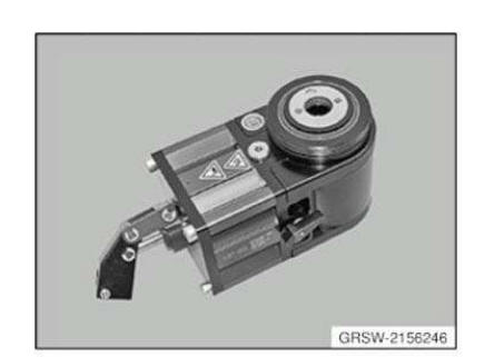
HYDRAULIC
Hydraulic cylinders AM
NOTE: Hydraulic cylinder (hydraulic actuator) in connection with lever, (81 64 2 156 247), for removal and installation of wheel bearings, propeller shafts and drive flanges.
SI number
08 06 09 (544)
Insert
Insert AM
NOTE: (Insert) Foam material insert (1 set = 2 pieces)
SI number
01 01 07 (333)
Insert AM
NOTE: (Insert) Foam insert, top.
Insert AM
NOTE: (Insert) Foam insert, bottom.
JOINT
Joint AM
SI number
01 01 07 (333)
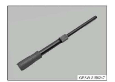
LEVER
Lever AM
NOTE: Lever in connection with hydraulic cylinder (hydraulic actuator), (81 64 2 156 246), for removal and installation of wheel bearings, propeller shafts and drive flanges.
SI number
08 06 09 (544)
Mandrel
Mandrel Mechanical tool
NOTE: (Drift) For driving in the retainer on the rear axle shaft
Storage Location
X8
Mandrel Mechanical tool
NOTE: (Guide mandrel) For fitting differential gear shaft into rear axle final drive
Storage Location
X4
Mandrel Mechanical tool
Replaced by: 83300492338
NOTE: (Drift) For radial seal on output flange - Replaced by 33 3 420. (0 492 338)
Mechanical Mandrel Minimum set: Mechanical tools 335080 tool
NOTE: For driving in shaft seal on drive shaft.
Storage Location
A16
SI number
01 21 06 (300)
Mandrel Mechanical tool
NOTE: (Drive-out mandrel) For the rear axle shaft/Replaced by 33 2 116. (0 492 175) and 33 4 200. (0 492 436)
Mandrel Mechanical tool
NOTE: (Drift) For driving in the retainer on the rear axle shaft (wheel bearing) and on the drive flange of the rear axle final drive (final drive types K and M)
Storage Location
A16
SI number
01 03 91 (333)
Mandrel Minimum set: Mechanical tools AM
NOTE: (Drift) For driving radial shaft seal of output shaft into rear axle final drive. Rear axle final drive: 215
Storage Location
B21
C21
SI number
01 01 07 (333)
Mandrel Mechanical tool
NOTE: (Drift) For driving in the radial seal rings in the rear axle final drive at the output flange with flange diameter 35 mm
Storage Location
X7
Mechanical Mandrel Minimum set: Mechanical tools 335130 tool
NOTE: For driving the radial shaft seal of the output shaft into the rear axle final drive.
Rear axle final drive: 188
Storage Location
C21
SI number
01 01 07 (333)
Mandrel Mechanical tool
Replaced by: 83300491891
NOTE: (Drift) Replaced by 31 2 040. (0 491 891)
Mandrel Minimum set: Mechanical tools Mechanical tool
NOTE: (Drift) For driving radial shaft seal onto drive flange. Replaced by 33 3 470/0 496 596
Storage Location
B26
SI number
01 09 09 (532)
Mandrel Mechanical tool
Replaced by: 83300492342
NOTE: (Drift) For driving the radial sealing ring into the output flange, flange diameter 43 mm - Replaced by 33 3 460. (0 492 342)
SI number
01 10 90 (288)
Mandrel Mechanical tool
Replaced by: 83300492338
NOTE: (Drift) For fitting the radial sealing ring, right-hand output end/Replaced by 33 3 420. (0 492 338)
Mandrel Mechanical tool
Replaced by: 83300492339
NOTE: (Drift) For driving the radial seal into the output flange with flange diameter 38 mm - Replaced by 33 3 430. (0 492 339)
Mandrel AM
NOTE: Discontinued, can only be ordered using complete tool
Nut
Nut Minimum set: Mechanical tools AM
NOTE: (Nut TR20)
Nut AM
Nut AM
NOTE: Liquidation of existing inventory and then available only as a complete tool set 33 2 120 = 83 30 0 492 179 - as of 09.12.2011
Nut Minimum set: Mechanical tools AM
NOTE: (Nut M12x1.5) discontinued, can only be ordered using complete tool
Storage Location
B22
SI number
01 01 07 (333)
Nut Minimum set: Mechanical tools AM
NOTE: (Thrust nut)
Nut AM
NOTE: Series: E30, E36
Nut AM
NOTE: (Nut with bearing) Model series: E28, E30, E31, E34, E36, RR1
Storage Location
C13
Nut AM
NOTE: (Nut with bearing) Model series: E28, E30, E83
Nut AM
Nut Minimum set: Mechanical tools AM
NOTE: (nut M12x1.5 (high wall))
SI number
01 16 08 (476)
Nut Minimum set: Mechanical tools AM
NOTE: (nut TR12 with thrust bearing)
Nut Minimum set: Mechanical tools AM
NOTE: (nut TR20 with thrust bearing)
Nut Minimum set: Mechanical tools AM
NOTE: (Nut with thrust piece) discontinued, can only be ordered using complete tool
SI number
01 01 07 (333)
OPEN-END WRENCH
Open-end wrench Mechanical tool
NOTE: (Open-end spanner SW17)
PIPE
Pipe Minimum set: Mechanical tools AM
NOTE: (Threaded tube) Deletion, only available via tool set
Plate
Plate AM
NOTE: (Shaped plate, top) For pulling in
Plate Minimum set: Mechanical tools AM
NOTE: (Fixing plate) With screws Deletion, only available via tool set
Plate AM
NOTE: (Shaped plate, bottom) For pulling in
Plate AM
NOTE: (Shaped plate, top) For removing
Plate AM
NOTE: (adapter plate) Transmission: GS6-57DZ, GS6-53BZ (G transmission) GS6-51DZ, GS6-51BZ (H transmission) Deletion, only available via tool set
Storage Location
C17
SI number
01 11 04 (093)
Pliers
Pliers AM
NOTE: (clamping ring (55...61 mm)) Model series: E67 No longer available separately, only via complete tool set 0493416 = 33 4 400.
Pliers AM
NOTE: (Clamping ring (50 to 55 mm)) No longer available separately, only available as part of complete tool set 0493416 = 33 4 400.
Pliers AM
NOTE: (Clamping ring (45 to 51 mm)) No longer available separately, only available as part of complete tool set 0493416 = 33 4 400.
Ring
Ring AM
NOTE: (pipe) For extracting and press-fitting the rubber mount in the 13º trailing arm
Ring AM
NOTE: (Clamping ring) Model series: F01, F02. Available only as complete special tool set 33 4 400.
SI number
01 18 08 (482)
RING SPANNER
Ring spanner Minimum set: Mechanical tools Mechanical tool
NOTE: Multi-tooth ring spanner SW65 For releasing and tightening down flange nut on rear axle final drive. Only ring spanners with a torque of 700 Nm may be used - as at 02/2014.
Storage Location
A18
SI number
01 21 06 (300)
Ring spanner Mechanical tool
NOTE: (Ring spanner WAF 19) For toe adjustment at the rear axle
Storage Location
X3
SI number
01 07 88 (972)
Ring spanner Minimum set: Mechanical tools AM
NOTE: (Reversible ratchet ring spanner SW24) discontinued, available as part of set of special tools only
SI number
01 01 07 (333)
Rod
Rod Minimum set: Mechanical tools AM
NOTE: (Guide rod) With thread dog point
Rod Minimum set: Mechanical tools AM
NOTE: (Guide rod)
Rod Minimum set: Mechanical tools AM
NOTE: Only available via complete tool set 33 5 120 -> (83 30 0 495 851).
SI number
01 01 07 (333)
Rod Mechanical tool
NOTE: (Split rod) For removing and installing the actuator unit of the active rear axle kinematics
SI number
01 01 92 (469)
Screw
Screw AM
NOTE: (Knurled screws (M16 2 x))
Screw AM
NOTE: (countersunk screws M10x30 (3 x)) Transmission: GS6-57DZ, GS6-53BZ (G transmission) GS6-51DZ, GS6-51BZ (H transmission) Deletion, only available via tool set
Storage Location
C17
SI number
01 11 04 (093)
Minimum set: Mechanical tools AM
NOTE: (Knurled screw with thrust piece) available as part of set of special tools 33 5 120 -> (83 30 0 495 851) only.
SI number
01 01 07 (333)
Screw AM
Screw AM
NOTE: Screws K1 (M12x1.5) for removal and installation of wheel bearings, propeller shafts and drive flanges.
SI number
08 06 09 (544)
Screw AM
NOTE: Screws K2 (M14x1.5) for removal and installation of wheel bearings, propeller shafts and drive flanges.
SI number
08 06 09 (544)
Shaped element
Shaped element Minimum set: Mechanical tools AM
NOTE: (Shaped element) shaped element (bearing shell) available as part of set of special tools 33 5 120 -> (83 30 0 495 851) only.
SI number
01 01 07 (333)
Shaped element AM
NOTE: For pulling the front rubber mounts out of the rear axle support, series: E36, E46
Storage Location
B13
C13
Shaped element AM
NOTE: For positioning the wishbone when pressing in the ball joint
Shaped element AM
NOTE: For pressing in
Shaped element AM
NOTE: For positioning when pressing out the ball joint
Shaped element AM
NOTE: For pressing in
Shaped element Minimum set: Mechanical tools Mechanical tool
NOTE: For pulling out rubber mounts in rear axle support mounting.
Storage Location
C29
SI number
01 22 11 (753)
Shaped element AM
NOTE: For pulling the rear rubber mounts out of the rear axle support, series: E36, E46
Storage Location
B13
Shaped element Minimum set: Mechanical tools AM
NOTE: Sale of existing inventory then available as part of set of tools 33 5 120 -> (83 30 0 495 851) only.
SI number
01 01 07 (333)
Shaped part
Shaped part AM
NOTE: (Shaped part)
Storage Location
Y8
SHAPED
Shaped part AM
NOTE: For removing the wheel bearing inner race from the drive flange hub in combination with special tool 33 4 400 and hydraulic tool 81 64 2 160 009.
Storage Location
C29
C30
SI number
01 15 11 (737)
SHAPED PART
Shaped part Minimum set: Mechanical tools AM
In conjunction with: 33 5 120 = 0495851
NOTE: For pressing output shaft out of rear axle final drive.
SI number
01 28 09 (600)
Shaped part Minimum set: Mechanical tools AM
NOTE: For driving output shaft into rear axle final drive.
SI number
01 28 09 (600)

Shaped part AM
NOTE: (Shaped part)
Shaped part Minimum set: Mechanical tools AM
NOTE: (Shaped part) 2 pieces Model series: E38, E39, E46 Deletion, only available via tool set
Storage Location
B8
Shaped part Minimum set: Mechanical tools AM
NOTE: (Shaped part)
Shaped part Minimum set: Mechanical tools AM
NOTE: (Shaped part) 2 pieces Model series: E39/2, E65, E67, RR1
Shell
Shell AM
Replaced by: 83300493416
NOTE: (Shell) Model series: E31, E38 Discontinuation and replaced by 33 4 400. (0 493 416)
Shell AM
Replaced by: 83300493416
NOTE: Discontinuation and replaced by 33 4 400 (0 493 416)

Shell AM
Replaced by: 83300493416
NOTE: (Shell) Model series: E31, E38 Discontinuation and replaced by 33 4 400. (0 493 416)

Shell AM
NOTE: (Bearing shell)
SOCKET NUT
Socket nut Minimum set: Mechanical tools Mechanical tool
NOTE: (Socket nut) z34 For holding the gearbox input shaft when releasing and tightening down flange nut.
Storage Location
A18
SI number
01 21 06 (300)
Socket wrench
Socket wrench AM
NOTE: (Socket wrench)
Socket wrench Minimum set: Mechanical tools AM
NOTE: (Socket wrench, hex socket, 6 mm) discontinued, available as part of set of special tools only
Socket wrench Minimum set: Mechanical tools AM
NOTE: (Socket wrench SW18) discontinued, available as part of set of special tools only
Socket wrench Minimum set: Mechanical tools AM
NOTE: (Socket wrench SW18) For releasing and tightening down support bearing screw connection.
Storage Location
A25
SI number
01 18 08 (482)
Consisting of:
1. Socket wrench
NOTE: (Socket wrench SW18) discontinued, available as part of set of special tools only
2. Socket wrench
NOTE: (Socket wrench, hex socket, 6 mm) discontinued, available as part of set of special tools only
Spindle
Spindle AM
NOTE: Discontinued, can only be ordered using complete tool
Spindle AM
NOTE: Spindle F3 (M24/270mm) in connection with adapter kit 1 (BMW), (81 64 2 155 745) and MINI adapter kit (81 64 2 294 517) for removal and installation of wheel bearings, propeller shafts and drive flanges.
SI number
08 06 09 (544)
Spindle AM
NOTE: For installing - model series: E28, E30, E31, E36
Storage Location
C13
Spindle Minimum set: Mechanical tools AM
NOTE: (spindle TR20 (length 300 mm))
Spindle AM
NOTE: (Threaded spindle, long) Series: E36/5 sale of existing inventory and then available as part of set of special tools 33 2 120 = 83 30 0 492 179 only - as of 09.12.2011
SI number
01 01 94 (766)

Spindle AM
NOTE: No longer available separately, only available as part of complete tool set 0493416 = 33 4 400.
Spindle AM
NOTE: Spindle F2 (M20/M24/355mm) in connection with adapter kit 1 (BMW), (81 64 2 155 745), and MINI adapter kit, (81 64 2 294 517), for removal and installation of wheel bearings, propeller shafts and drive flanges.
SI number
08 06 09 (544)
Spindle AM
NOTE: (Spindle for installation) Model series: E28, E30, E31, E36, RR1
Storage Location
C13
Spindle AM
NOTE: Series: E28, E30, E83
Spindle Minimum set: Mechanical tools AM
NOTE: (spindle 205 mm, M12)
Spindle Minimum set: Mechanical tools AM
NOTE: Discontinued, can only be ordered using complete tool
SI number
01 01 07 (333)
Spindle AM

Spindle AM
NOTE: For removing and installing front/rear rubber mounts in rear axle support
Storage Location
B13
SI number
01 10 90 (288)
Consisting of:
1. Shaped element
NOTE: For pulling the rear rubber mounts out of the rear axle support, series: E36, E46
2. Washer
NOTE: (Thrust washer) For installing the front/rear rubber mount, series: E36, E46
3. Shaped element
NOTE: For pulling the front rubber mounts out of the rear axle support, series: E36, E46
4. Spindle
NOTE: For pulling out the front rubber mount, series: E36, E46
Spindle AM
NOTE: (Spindle, short)
Spindle AM
Replaced by: 83300493416
NOTE: Discontinuation and replaced by 33 4 400. (0 493 416)
Spindle Minimum set: Mechanical tools AM
NOTE: (spindle TR12)
SI number
01 16 08 (476)
Spindle Minimum set: Mechanical tools AM
In conjunction with: 33 4 030, 33 4 040 = 0492359
NOTE: (spindle TR20 with nut)
SI number
01 16 08 (476)
Consisting of
1. Spindle
NOTE: (spindle TR20 (length 300 mm))
2. Nut
NOTE: (nut TR20 with thrust bearing)
3. Nut
NOTE: (Nut TR20)
Spindle AM
NOTE: Spindle F1 (M24/425 mm) in connection with adapter kit 1 (BMW), (81 64 2 155 745), for removal and installation of wheel bearings, propeller shafts drive flanges.
SI number
08 06 09 (544)
Spindle AM
Replaced by: 83300492222
NOTE: Replaced by 33 3 107. (0 492 222)
Spindle Minimum set: Mechanical tools AM
NOTE: (spindle TR12 with nut)
SI number
01 16 08 (476)
Consisting of:
1. Spindle
NOTE: (spindle TR12)
2. Nut
NOTE: (nut TR12 with thrust bearing)
3. Nut
NOTE: (nut M12x1.5 (high wall))
Spindle AM
Spindle AM
NOTE: For pulling out the front rubber mount, series: E36, E46
Storage Location
B13
C13
Spindle AM
NOTE: (Spindle with pressure pad)
Spring cups
Spring cups AM
NOTE: (spring cup, top)
Spring cups Minimum set: Mechanical tools AM
NOTE: Discontinued, can only be ordered using complete tool
SI number
01 01 07 (333)
Spring cups AM
NOTE: (spring cup, bottom)
Spring cups Minimum set: Mechanical tools AM
NOTE: Discontinued, can only be ordered using complete tool
SI number
01 01 07 (333)
Spring tensioner
Spring tensioner AM
NOTE: For tensioning coil springs when removing and installing coil springs and/or shock absorbers
SI number
01 05 90 (207)
Consisting of:
1. Spring cups
NOTE: (spring cup, top)
2. Spring cups
NOTE: (spring cup, bottom)
3. Synchronising key
NOTE: (synchronising key, complete)
4. Spindle
5. Nut
6. Socket wrenchNOTE: (Socket wrench)
Spring tensioner Minimum set: Mechanical tools AM
NOTE: For tensioning or removing and installing barrel spring on rear axle.
SI number
01 01 07 (333)
Consisting of:
1. Spring cups
NOTE: Discontinued, can only be ordered using complete tool
2. Spring cups
NOTE: Discontinued, can only be ordered using complete tool
3. Spindle
NOTE: Discontinued, can only be ordered using complete tool
4. Nut
NOTE: (Nut with thrust piece) discontinued, can only be ordered using complete tool
5. Ring spanner
NOTE: (Reversible ratchet ring spanner SW24) discontinued, available as part of set of special tools only
6. Case
NOTE: (Case) Case with insert discontinued, can only be ordered using complete tool
Synchronising key
Synchronising key AM
Storage Location
Y4
Synchronising key AM
NOTE: For ball bearing, inner
Synchronising key AM

Synchronising key AM
NOTE: (Thrust piece (for removing)) Deletion, only available via tool set
Storage Location
C53
SI number
01 18 05 (214)
Synchronising key AM
NOTE: For pressing the rubber mount out of the rear axle final drive mounting Series: E31
Storage Location
C14

Synchronising key AM
NOTE: (thrust piece and pipe) For extracting and press-fitting the rotation slide bearing and rubber mount in the 13º trailing arm
Storage Location
X10
Consisting of:
1. Synchronising key
NOTE: For removing and installing the rotary slide mount in the 13º trailing arm/Series: E34, E32/Model: M5, 750i
2. Ring
NOTE: (pipe) For extracting and press-fitting the rubber mount in the 13º trailing arm
Synchronising key AM
NOTE: For pressing the ball joint out of the engine support arm or wheel carrier
Storage Location
X5
Synchronising key Minimum set: Mechanical tools AM
NOTE: (Synchronising key (2 x)) With countersunk screw - model series: E39/2, E65, E67, E87
SI number
01 15 04 (117)
Synchronising key AM
NOTE: Series: F01, F02. Remaining inventories will be sold off and then it will no longer be available separately, only available as part of complete tool set 0493416 = 33 4 400.
Synchronising key AM
NOTE: Series: E28, E30 Model: 316 - 323i discontinued, available as part of set of special tools only
Synchronising key AM
NOTE: For pressing out the front rubber mount
Storage Location
X5
Synchronising key AM
NOTE: For removing and installing the rotary slide mount in the 13º trailing arm/Series: E34, E32/Model: M5, 750i
Synchronising key Mechanical tool
NOTE: For removing rubber mount in rear axle support (E46/5)
SI number
01 12 01 (743)
Synchronising key AM
Replaced by: 83300493416
NOTE: (Synchronising key) Model series: E38, E39 Discontinuation and replaced by 33 4 400. (0 493 416)
Synchronising key AM
Storage Location
Y4
Synchronising key AM
Synchronising key AM
NOTE: For pressing out the rubber mount from the wishbone
Synchronising key AM
NOTE: (synchronising key, complete)
Synchronising key Minimum set: Mechanical tools AM
NOTE: (Synchronising key (2 x)) With screws - model series: E38, E39, E46 Deletion, only available via tool set
Storage Location
B8
Synchronising key AM
NOTE: (Thrust piece (for installing)) Deletion, only available via tool set
Storage Location
C53
SI number
01 18 05 (214)
Synchronising key AM
NOTE: For pressing the rubber mount out of the leading link
Storage Location
Z8
Synchronising key AM
NOTE: (Synchronising key) Model series: E28, E30 Model: 518 - 735i discontinued, available as part of set of special tools only
Synchronising key AM
NOTE: Not available individually. Only via complete tool set
Storage Location
Y4
Synchronising key AM
NOTE: For pulling the bearing inner race off the drive flange - Series: E36/5 Discontinued, only available via complete tool
Storage Location
Y4
SI number
01 01 94 (766)
Synchronising key AM
NOTE: For ball bearing, outer
Synchronising key AM
NOTE: (Thrust piece (old)) Discontinued, only available via complete tool
Storage Location
Y4
Synchronising key Mechanical tool
NOTE: For removing and installing the rubber mounts in the 13º trailing arm
Storage Location
X10
Synchronising key AM
NOTE: For rear axle differential and for installing the camshaft sprocket on the crankshaft (M70) Discontinued, only available via complete tool
Storage Location
Y4
TENSIONING STRAP
Tensioning strap Mechanical tool
NOTE: For removing and installing the pressure accumulator for the hydraulic unit of the rear axle differential lock
Storage Location
X10
Y10
SI number
01 07 92 (516)
Tool
Tool AM
NOTE: (Set of pressing-in/pressing-out tools) Form pressing in and pressing out the ball joint position in the supporting arm and wheel carrier
Storage Location
X5
SI number
01 05 90 (207)
Consisting of:
1 = Bush
NOTE: For accommodating the engine support arm or wheel carrier when pressing out the ball joint
2 = Synchronising key
NOTE: For pressing the ball joint out of the engine support arm or wheel carrier
3 = Holding sleeve
NOTE: (Spacer sleeve) For pressing the ball joint into the support arm
3 = Holding sleeve
NOTE: (Spacer sleeve) For pressing the ball joint into the wheel carrier
Tool AM
Replaced by: 83300493416
NOTE: For removing the bearing shell on the rear axle shaft. Replaced by 33 4 400. (0 493 416)
Storage Location
Y5
Consisting of:
1. Shell
NOTE: (Bearing shell)
2. Shell
NOTE: Discontinuation and replaced by 33 4 400 (0 493 416)
3. Holding sleeve
4. Spindle
Tool AM
NOTE: For removing and installing rubber mount in rear axle support
Storage Location
A14
Consisting of:
1 = Washer
NOTE: (Shaped washer) For pulling out the top rubber mount Series: E30, E36
2 = Washer
NOTE: (Shaped washer) For installing the bottom rubber mount Series: E30, E36
3 = Washer
NOTE: (Form disc) Replaced by 33 3 115. (0 492 227)
5 = Washer
NOTE: (Shaped washer) For gripping when installing
4 = Nut
NOTE: Series: E30, E36
Tool Mechanical tool
NOTE: For pulling off drive flanges
Tool AM
NOTE: (extraction/press-fit tool set) For extracting and press-fitting the rubber mounts into the leading link
Storage Location
Z8
SI number
01 05 90 (207)
Consisting of:
1. Bush
NOTE: For accommodating the leading link when pressing out
2. Synchronising key
NOTE: For pressing the rubber mount out of the leading link
3. Holding sleeve
NOTE: (spacer sleeve) For press-fitting the rubber mount into the leading link
4. Holding sleeve
NOTE: (spacer sleeve) For press-fitting the ball joint in the wheel carrier
Tool AM
NOTE: To pull in the wheel bearings and radial seals on the rear axle - model year: up to 82 (E23, E24)
Consisting of:
1. Synchronising key
NOTE: For ball bearing, outer
2. Synchronising key
NOTE: For ball bearing, inner
Tool Minimum set: Mechanical tools AM
NOTE: For removing and installing camber arm rubber mount on rear axle support.
Storage Location
B49
C49
SI number
01 15 04 (117)
Consisting of:
1. Washer
NOTE: (draw-in disc)
2. Washer
NOTE: (pull-out disc)
3. Holder
NOTE: (Countersupport) 0496208 =119850
4. Holding sleeve
NOTE: (support sleeve)
5. Spindle
NOTE: (spindle 205 mm, M12)
6. Nut
NOTE: (Thrust nut)
Tool AM
NOTE: (Extraction tool and press-in tool set) for extracting and pressing in the rubber mount in the wishbone/rubber mount in the wishbone not available separately as replacement part
SI number
01 05 90 (207)
Consisting of:
1. Bush
NOTE: For holding the wishbone when pressing out the rubber mount
2. Synchronising key
NOTE: For pressing out the rubber mount from the wishbone
3. Holding sleeve
NOTE: (Spacer sleeve) for pressing in the rubber mount in the wishbone
Tool AM
NOTE: (Pressing-in/out tool set) for removing and installing the rubber mount on the front trailing arm
Storage Location
X5
SI number
01 05 90 (207)
Consisting of:
1. Bush
NOTE: For accommodating the trailing arm when pressing out
2. Synchronising key
NOTE: For pressing out the front rubber mount
3. Holding sleeve
NOTE: (Guide sleeve) to press in the front rubber mount
Tool AM
NOTE: (extractor/press-fit tool set) For extracting and press-fitting the rubber mount in the differential carrier
Storage Location
C14
SI number
01 05 90 (207)
Consisting of:
1. Bush
NOTE: Series: E31, E46
2. Synchronising key
NOTE: For pressing the rubber mount out of the rear axle final drive mounting Series: E31
3. Holding sleeve
NOTE: (spacer sleeve) For pressing the rubber mount into the differential carrier - Series: E31
Tool AM
NOTE: (Tool set) For removing and installing rubber mounts in rear axle support
Storage Location
C13
Consisting of:
1. Spindle
NOTE: Replaced by 33 3 107. (0 492 222)
2. Washer
NOTE: (Shaped washer) For removing - model series: E28
3. Spindle
NOTE: (Spindle for installation) Model series: E28, E30, E31, E36, RR1
4. Nut
NOTE: (Nut with bearing) Model series: E28, E30, E31, E34, E36, RR1
5. Washer
NOTE: (Shaped washer) For installing - model series: E28
6. Washer
NOTE: (Shape washer) For counter support during installing - model series: E28
7. Spindle
NOTE: For installing - model series: E28, E30, E31, E36
Tool AM
Replaced by: 83300493416
NOTE: (Tool set) For removing bearing inner race from drive flange (rear wheel bearing) - Replaced by 33 4 400. (0 493 416)
Storage Location
C28
SI number
01 05 90 (207)
Consisting of:
1. Shell
NOTE: (Shell) Model series: E31, E38 Discontinuation and replaced by 33 4 400. (0 493 416)
2. Shell
NOTE: (Shell) Model series: E31, E38 Discontinuation and replaced by 33 4 400. (0 493 416)
3. Bush
NOTE: (Clamping bush) Discontinuation and replaced by 33 4 400. (0 493 416)
4. Spindle
NOTE: Discontinuation and replaced by 33 4 400. (0 493 416)
5. Synchronising key
NOTE: (Synchronising key) Model series: E38, E39 Discontinuation and replaced by 33 4 400. (0 493 416)
Tool AM
NOTE: (tool set) For removing and fitting the rubber mounts in the rear axle support, lateral
Storage Location
Y9
SI number
01 04 88 (566)
Consisting of:
1. Washer
NOTE: (Extractor disc) sale of existing inventory and then available as part of complete tool set 33 3 120 = 83 30 0 492 228 only - as of 29.11.2011
2. Washer
NOTE: (Installation disc) Liquidation of existing inventory and then available only via complete tool set 33 3 120 = 83 30 0 492 228 - status 29.11.2011
3. Washer
NOTE: For counter support when pulling in Only available via complete tool set 33 3 120 = 83 30 0 492 228 - status 29.11.2011
Tool AM
Replaced by: 83300492436
NOTE: (Tool set) For pulling out rear drive flange from wheel bearing - replaced by 33 4 200. (0 492 436)
Consisting of:
1. Spindle
NOTE: (Spindle with pressure pad)
2. Basic unit
NOTE: Discontinuation and replaced by 33 4 200. (0 492 436)
Tool Mechanical tool
NOTE: To pull off of ball bearings from the drive shaft (pinion head) - discontinued on 18.01.95
Tool AM
NOTE: (Tool supplement) For 33 1 350, 33 1 360, 33 1 356, 33 1 362, 33 1 363 and 33 1 358
Storage Location
Y8
Consisting of:
1. Shaped part
NOTE: (Shaped part)
2. Washer
NOTE: (Thrust washer)
3. Washer
NOTE: (Installation washer) For bearing shell (engine on inside)
4. Washer
NOTE: (Installation disc) for bearing shell (outside drive) discontinued, available as part of set of special tools only
Tool Minimum set: Mechanical tools AM
NOTE: (tool set) For removing and installing trailing arm rubber mount on rear axle support.
Storage Location
B49
SI number
01 15 04 (117)
Consisting of:
1. Washer
NOTE: (draw-in disc)
2. Washer
NOTE: (pull-out disc)
3. Washer
NOTE: (draw-in disc)
4. Holding sleeve
NOTE: (support sleeve)
5. Holder
NOTE: (Countersupport) 0496208 =119850
Tool AM
NOTE: (Tool set) Complete tool set in a case, for removing and installing the rubber mounts in the rear axle support. The case contains the following special tools: - 33 3 314/315 - 33 3 370 - 33 4 140 - 33 4 150 - 33 4 210
SI number
01 19 03 (017)
Consisting of:
1. Case
NOTE: (Case) with label.
2. Insert
NOTE: (Insert) Foam insert, bottom.
3. Insert
NOTE: (Insert) Foam insert, top.
Tool set AM
NOTE: Threaded spindle set for removing and installing the rubber mount on the rear axle support.
SI number
08 06 10 (658)
Consisting of:
4 = 2208574
3 = 2208575
2 = 2208576
1 = 2208577
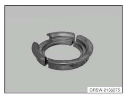
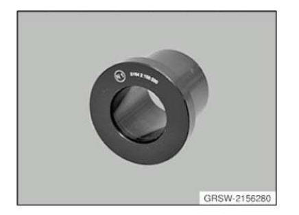
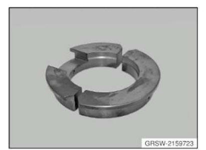
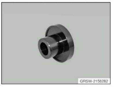
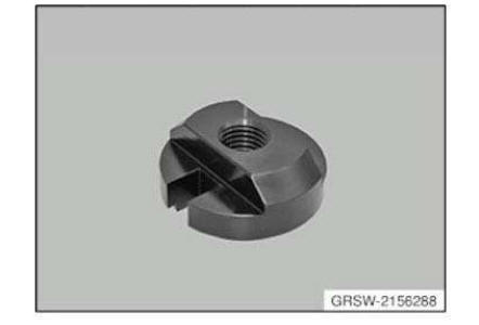
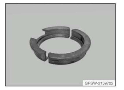
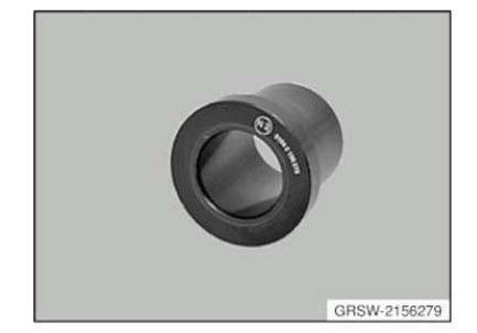
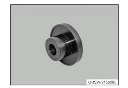
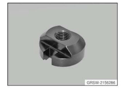
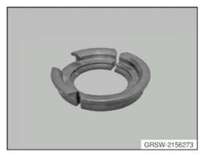
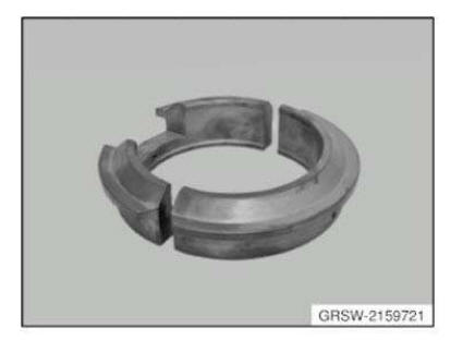
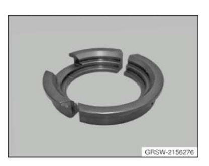
Tool set AM
NOTE: Adapter kit 2 (BMW), (BMW-specific adapters), for installation and removal of wheel bearings, propeller shafts and drive shafts.
SI number
08 12 14 (155)
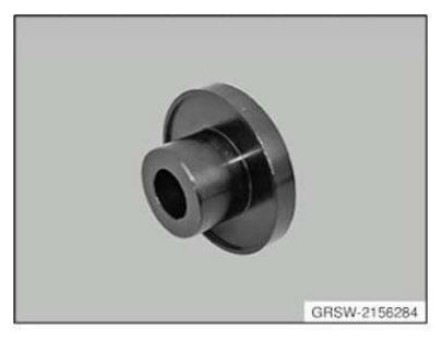
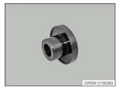
Consisting of:
1 = 2159721
14 = 2159722
18 = 2156282
17 = 2156283
2 = 2159723
16 = 2156275
15 = 2156273
13 = 2156280
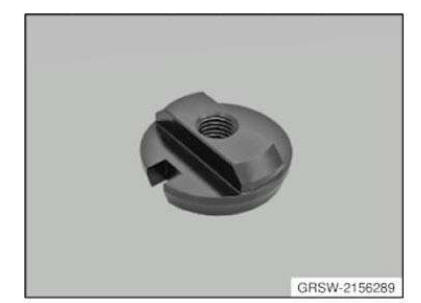
12 = 2156279
11 = 2156278
10 = 2156277
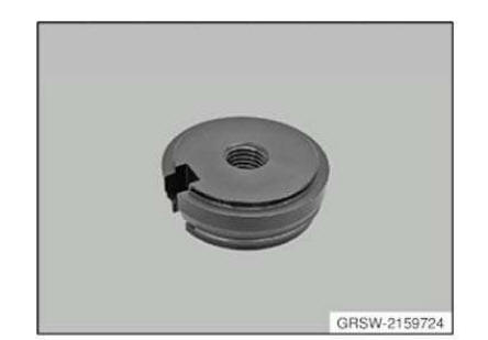
3 = 2156285
4 = 2159724
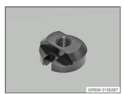
5 = 2156289
6 = 2156288
7 = 2156287
8 = 2156286
9 = 2156284
Tool set AM
NOTE: A set of the BMW hydraulic tool system for wheel bearings and output shafts (basic set for BMW, consisting of 81 64 2 155 744, 81 64 2 155 745, 81 64 2 155 746)
SI number
08 12 14 (155)
Tool set AM
NOTE: Hydraulic unit (basic unit) for removal and installation of wheel bearings, propeller shafts and drive flanges.
SI number
08 12 14 (155)
Consisting of:
2 = 2156247
1 = 2156246
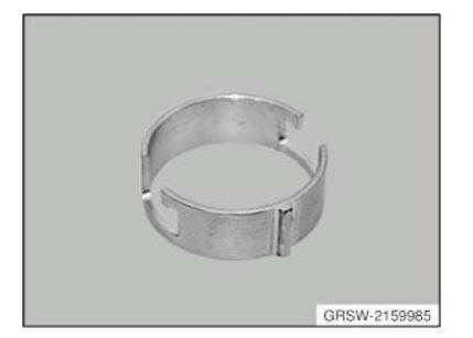
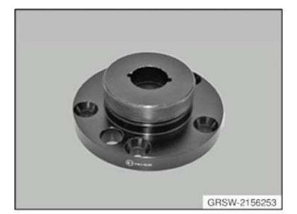
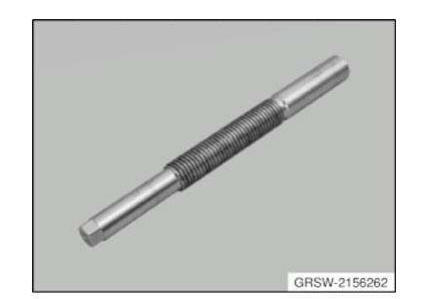
Tool set AM
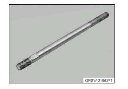
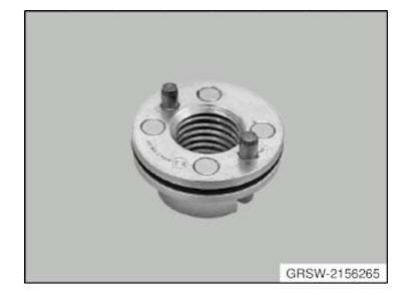
NOTE: Wheel bearing adapter kit 1 (BMW), (spindles and tensioning nuts) for removal and installation of wheel bearings, propeller shafts and drive flanges.
SI number
08 12 14 (155)
Consisting of:
15 = 2156262
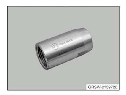
14 = 2159720
13 = 2156257
12 = 2156256
11 = 2318476
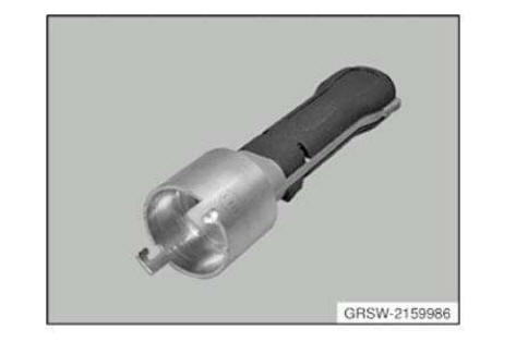
10 = 2159986
9 = 2159985
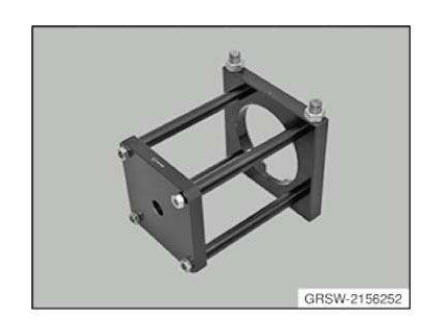
1 = 2156252
2 = 2156253
3 = 2156254
4 = 2156255
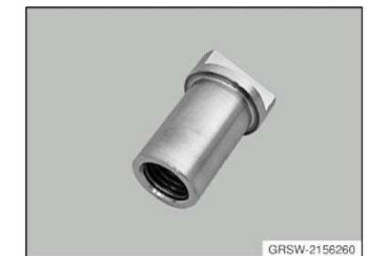
5 = 2156258
6 = 2156260
7 = 2156265
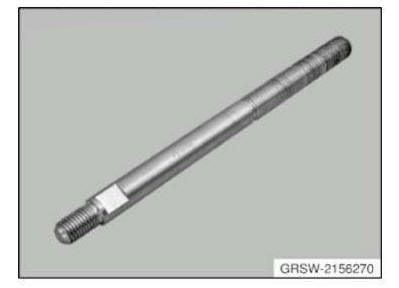
8 = 2156271
16 = 2156270
UPHOLSTERY
Upholstery AM
SI number
01 01 07 (333)
Washer
Washer Minimum set: Mechanical tools AM
NOTE: For installing ball joint in rear wheel carrier (bottom camber control arm)
Storage Location
C30
SI number
01 22 11 (753)
Washer AM
NOTE: For counter support when pulling in Only available via complete tool set 33 3 120 = 83 30 0 492 228 - status 29.11.2011
Washer Minimum set: Mechanical tools Mechanical tool
Replaced by: 83300494797
NOTE: (Shim) For removing and installing output shaft in drive flange, front and rear, as well as for removing front wheel bearing unit. Replaced by 33 2 160 (0 494 797)
SI number
01 15 99 (483)
Washer Minimum set: Mechanical tools Mechanical tool
NOTE: For installing rubber mount in rear wheel carrier (bottom trailing arm).
Storage Location
C30
SI number
01 22 11 (753)
Washer AM
NOTE: (Measuring disc)
Washer AM
NOTE: (Measuring disc)
Washer Minimum set: Mechanical tools AM
NOTE: (draw-in disc)
Storage Location
B49
Washer Minimum set: Mechanical tools AM
NOTE: (pull-out disc)
NOTE: (Installation disc) Liquidation of existing inventory and then available only via complete tool set 33 3 120 = 83 30 0 492 228 - status 29.11.2011
Washer AM
NOTE: (Installation washer) For bearing shell (engine on inside)
Storage Location
Y8
Washer AM
NOTE: (Shape washer) For counter support during installing - model series: E28
Storage Location
C13
Washer Minimum set: Mechanical tools AM
NOTE: Discontinued, can only be ordered using complete tool
Storage Location
B22
SI number
01 01 07 (333)
Washer AM
NOTE: (Shaped washer) For gripping when installing
Washer AM
NOTE: (Washer without thread)
Washer AM
NOTE: (Shaped washer) For removing - model series: E28
Storage Location
C13

Washer AM
NOTE: (Installation washer (2 pieces))
Washer AM
NOTE: Contact disc D1 in connection with adapter kit 1 (BMW), (81 64 2 155 745) and MINI adapter kit (81 64 2 294 517), for removal and installation of wheel bearings, propeller shafts and drive flanges.
SI number
08 06 09 (544)
Washer AM
NOTE: (Disc) Discontinued, only available via complete tool
Storage Location
Y4
Z4
Washer AM
NOTE: (Extractor disc) sale of existing inventory and then available as part of complete tool set 33 3 120 = 83 30 0 492 228 only - as of 29.11.2011
Washer AM
NOTE: (Thrust washer)
Storage Location
Y8
Washer AM
Replaced by: 83300492107
NOTE: (Disc) Replaced by 33 1 311. (0 492 107)
Washer AM
NOTE: (Thrust washer) For installing the front/rear rubber mount, series: E36, E46
Storage Location
B13
Washer Minimum set: Mechanical tools Mechanical tool
NOTE: For removing ball joint in rear wheel carrier (bottom camber arm).
Storage Location
C29
SI number
01 22 11 (753)
Washer AM
NOTE: (Shaped washer) For installing - model series: E28
Storage Location
C13
Washer AM
Replaced by: 83300492107
NOTE: (Disc) Replaced by 33 1 311. (0 492 107)
Washer Minimum set: Mechanical tools Mechanical tool
NOTE: For installing rubber mounts in rear axle support mounting.
Storage Location
C29
SI number
01 22 11 (753)
Washer Minimum set: Mechanical tools AM
NOTE: (pull-out disc)
Storage Location
B49
Washer Minimum set: Mechanical tools AM
NOTE: Discontinued, can only be ordered using complete tool
Storage Location
A22
SI number
01 01 07 (333)
Washer Minimum set: Mechanical tools AM
NOTE: Discontinued, can only be ordered using complete tool
Storage Location
A22
SI number
01 22 06 (307)
Washer Minimum set: Mechanical tools AM
NOTE: (draw-in disc)
Washer Mechanical tool
NOTE: For driving in the radial shaft seal on the input flange
Washer AM
NOTE: (Shaped washer) For pulling out the top rubber mount Series: E30, E36
Washer Minimum set: Mechanical tools Mechanical tool
NOTE: For installing rubber mounts in rear axle support mounting.
Storage Location
C29
SI number
01 22 11 (753)

Washer AM
NOTE: (Measuring disc)
Washer AM
NOTE: Contact disc (M24) E3 in connection with adapter kit 1 (BMW), (81 64 2 155 745) and MINI adapter kit (81 64 2 294 517), for removal and installation of wheel bearings, propeller shafts and drive flanges.
SI number
08 06 09 (544)
Washer AM
NOTE: (Installation disc) for bearing shell (outside drive) discontinued, available as part of set of special tools only
Storage Location
Y8
Washer AM
Washer AM
Washer AM
NOTE: (Measuring disc)
Washer Minimum set: Mechanical tools AM
NOTE: For removing rubber mounts in rear wheel carrier (top wishbone and bottom trailing arm)
Storage Location
C30
SI number
01 22 11 (753)
Washer Minimum set: Mechanical tools AM
NOTE: (draw-in disc)
Storage Location
B49
Washer Minimum set: Mechanical tools AM
NOTE: For installing rubber mount in rear wheel carrier (top wishbone).
Storage Location
C29
SI number
01 22 11 (753)
Washer AM
NOTE: (Shaped washer) For installing the bottom rubber mount Series: E30, E36
Washer AM
Replaced by: 83300492107
NOTE: (Disc) Replaced by 33 1 311. (0 492 107)
Washer AM
NOTE: (Thrust washer)

Washer AM
NOTE: (Washer with thread)
Washer AM
NOTE: (Measuring disc)
Washer Mechanical tool
NOTE: (Shaped disc) For pulling the rubber mount out of the front trailing arm
Storage Location
A14
SI number
01 10 90 (288)
Washer AM
Replaced by: 83300492227
NOTE: (Form disc) Replaced by 33 3 115. (0 492 227)
Wrench
Wrench AM
NOTE: (Ignition key) Discontinued, only available via complete tool
Wrench Minimum set: Mechanical tools AM
In conjunction with: 33 5 070 = 0495554
NOTE: For loosening and tightening the propeller shaft to rear axle final drive screw connection (slot nut). SW50. Replaces SWZ 33 5 040 (0495551) as well from 09/2014.
Storage Location
B28
SI number
01 11 10 (641)
Wrench AM
NOTE: (Ignition key) Discontinued, only available via complete tool
GENERAL - TRACK WIDTH
GENERAL - TRACK WIDTH SPECIFICATION
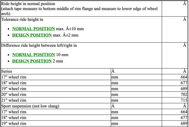
TED-TED-TDMUC3300-F25_HOEHEB1S1 REAR AXLE - RIDE HEIGHT, BMW, F25
REAR AXLE - RIDE HEIGHT F25
REAR AXLE - RIDE HEIGHT SPECIFICATION

REAR AXLE FINAL DRIVE, 188LW
REAR AXLE FINAL DRIVE SPECIFICATION

REAR AXLE FINAL DRIVE, 215LW
REAR AXLE FINAL DRIVE SPECIFICATION

ANTI-ROLL BAR
TIGHTENING TORQUE SPECIFICATION - ANTI-ROLL BAR
REAR AXLE SUSPENSION
TIGHTENING TORQUE SPECIFICATION - REAR AXLE SUSPENSION
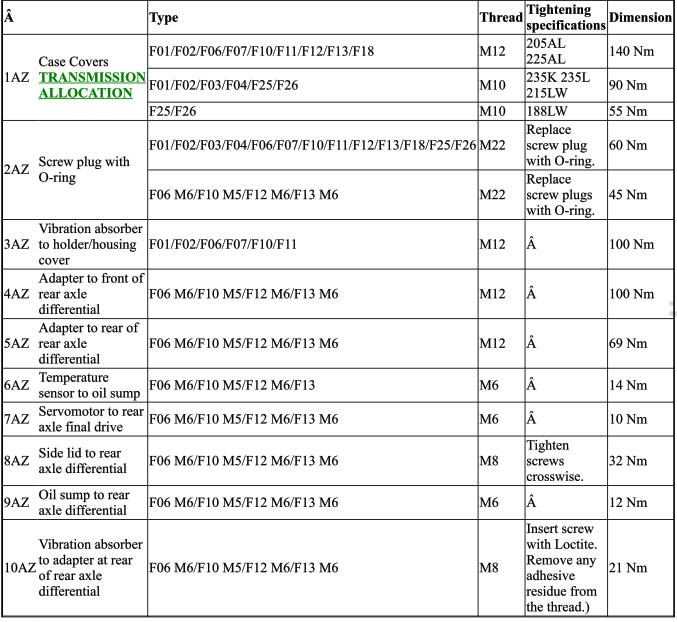
REAR DIFFERENTIAL CASE WITH COVER
TIGHTENING TORQUE SPECIFICATION - REAR DIFFERENTIAL CASE WITH COVER
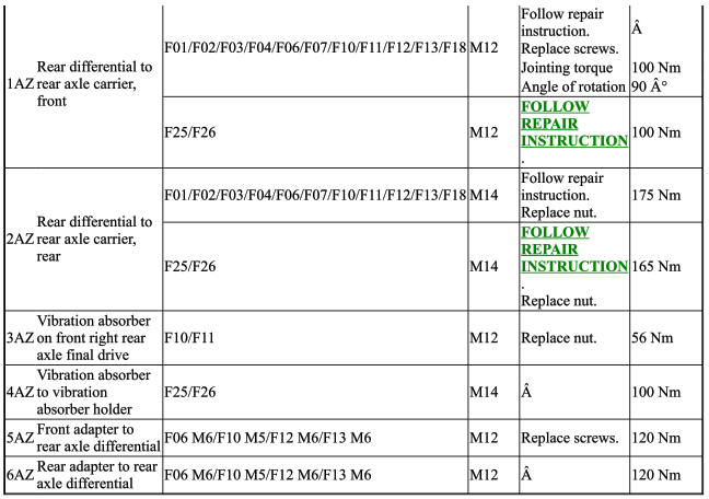
REAR AXLE DIFFERENTIAL MOUNTINGS
TIGHTENING TORQUE SPECIFICATION - REAR AXLE DIFFERENTIAL MOUNTINGS

SHOCK ABSORBERS
TIGHTENING TORQUE SPECIFICATION - SHOCK ABSORBERS
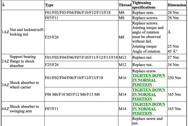
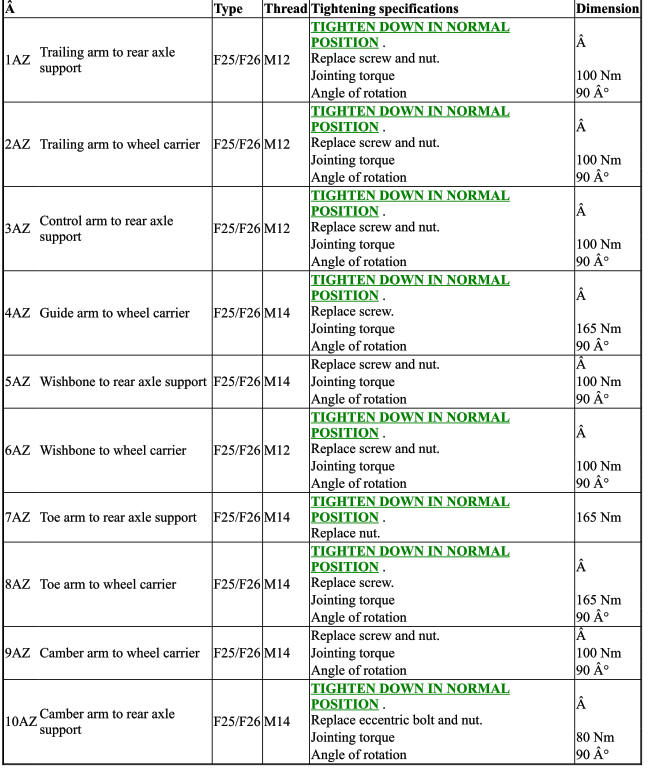
TRAILING ARMS AND STRUTS
TIGHTENING TORQUE SPECIFICATION - TRAILING ARMS AND STRUTS
WHEEL BEARINGS
TIGHTENING TORQUE SPECIFICATION - WHEEL BEARINGS
 Stabilizer bar
...
 General information on final drive oil
1.0 GENERAL INFORMATION ON FINAL DRIVE OIL
Final Drive oil or hypoid gear lubricant must conform with the following requirements because of the hig ...
Other materials:
BMW X3 (F25) Service & Repair Manual > Suspension: Spring with suspension
MEASURING VEHICLE RIDE HEIGHT
Determine actual ride height (A) - to do so, attach tape measure to rim flange (2) at bottom middle and measure
to wheel arch lower edge (1).
Removing and installing/replacing coil spring for front left or front right
spring strut
Special tools required:
31 ...
