BMW X3 (F25) Service & Repair Manual: Electronic chassis alignment
- Additional work for camber correction
- Adjusting rear axle
- Adjusting toe-in on front axle
- Danger of poisoning if oil is ingested/absorbed through the skin
- General information and definitions
- Kds chassis/wheel alignment check with vehicle load up to design position
- Kds wheel alignment check with ride height measurement without vehicle load
- Moving vehicle into design position
- Notes on replacement of steering gear/steering column/steering shaft following accident damage
- Rear axle: wheel alignment check must be carried out after the following work
- Risk of injury if oil comes into contact with eyes and skin
- Safety information for working on vehicles with automatic engine start-stop function (msa)
- Safety instructions for handling oil
Additional work for camber correction
IMPORTANT: Changes in axle geometry caused by accidents must under no circumstances be rectified by camber adjustment!
NOTE: The swivel bearing may only be replaced if the camber is outside the specified tolerance after toe adjustment.
Necessary preliminary tasks:
Adjust TOE-IN.
Check camber values; if necessary, replace swivel bearing .
NOTE: Camber correction swivel bearings are marked with an -/+ and, if applicable, with a color coding/part number at position (1)
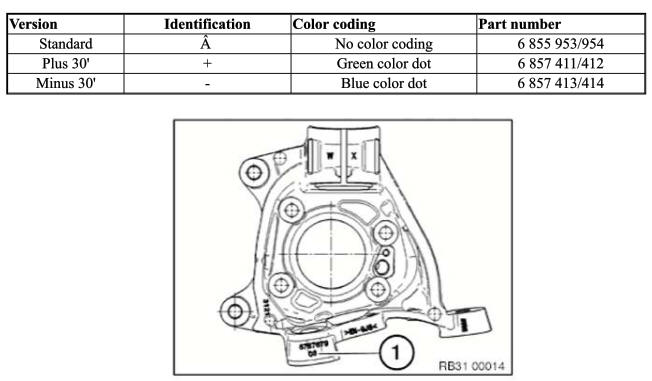
These camber correction swivel bearings are used to correct the camber values by 30 min. To be used only if the tolerance values are exceeded or undershot!
After Installation note:
- Check directional stability of car; if necessary, repeat TOE-IN adjustment.
Adjusting rear axle
NOTE: A camber change always means a toe change as well. The camber must therefore be adjusted first.
Adjusting camber:
Renew nut (1) and eccentric bolt (2) and tighten to 5 Nm.
Turn eccentric bolt (2) to adjust camber to setpoint value.
Tighten nut (1).
Adjusting toe:
Renew nut (2) and eccentric bolt (1) and tighten to 5 Nm.
Turn eccentric bolt (1) to adjust toe to setpoint value.
Tighten nut (2).
Adjusting toe-in on front axle
NOTE: Camber and toe-in influence each other. Adjust the toe-in first in order to simplify the adjustment procedure.
Version with active steering:
- Align steering wheel.
- Set total steering angle by means of the service function "Carry out initial operation/adjustment for active steering" to "zero".
- If necessary, secure with steering wheel arrester.
Version without active steering:
Remove front UNDERBODY PROTECTION .
Move steering into straight-ahead driving position by means of markings on cap (1) and steering box (2).
Align steering wheel and secure with steering wheel arrester.
Clean thread on track rod.
Slacken clamping nut (2), gripping track rod end (1) in the process.
Remove clamp (4).
Turn track rod (3) to adjust toe-in to setpoint value.
Version with active steering: Check total steering angle; if necessary, set to "zero".
Check toe values, repeat adjustment if necessary.
Tighten down clamping nut (2).
Fit clamp (4).
After installation:
- Check directional stability of vehicle; if necessary, repeat toe-in adjustment
Danger of poisoning if oil is ingested/absorbed through the skin
Danger of poisoning! Ingesting oil or absorbing through the skin may cause poisoning!
Possible symptoms are:
- Headaches
- Dizziness
- Stomach aches
- Vomiting
- Diarrhoea
- Cramps/fits
- Unconsciousness
Protective measures/rules of conduct:
- Pour oil only into appropriately marked containers
- Do not pour oil into drinking vessels (drinks bottles, glasses, cups or mugs)
- Observe country-specific safety regulations
First aid measures:
- Do not induce vomiting.
If the person affected is still conscious, he/she must rinse out their mouth with water, drink plenty of water and consult a doctor immediately.
If the person affected is unconscious, do not administer anything by mouth, place the person in the recovery position and seek immediate medical attention.
FRONT AXLE + STEERING: WHEEL ALIGNMENT CHECK MUST BE CARRIED OUT AFTER THE FOLLOWING WORK
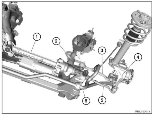
A WHEEL ALIGNMENT CHECK must be carried out after the following work:
Release the following screw connections:
- Steering box to front axle support
- Lower wishbone to front axle support
- Track rod end to track rod
Replace the following components:
- Steering box (1)
- Front axle support (2)
- Wishbone, bottom (3)
- Swivel bearing (4)
- Track rod end (5)
- Track rod (6)
GENERAL CHASSIS AND SUSPENSION DEFINITIONS
General information and definitions
Toe angle difference
a - Toe difference angle
D - Center point of operating circle
The toe angle difference is the angle adjustment of the inner cornering wheel relative to the outer cornering wheel when negotiating a curve. Steering is designed in such a way that angular position of wheels changes as steering lock progresses.
A correctly adjusted toe angle difference produces equal values for left and right lock with consideration of factory tolerances.
Toe angle difference provides information on corresponding operation of steering trapezoid for left or right steering lock from center position.
Camber
Inclination of the wheel from the perpendicular.
Toe
Reduction in distance of front of front wheels to rear of front wheels. The toe-in prevents the wheels from moving apart during driving and thus:
- the wheels from vibrating and grinding
- excessive tire wear
- excessive strain on the steering linkage and its links/joints
- heavy vehicle steering
Measurement is performed in "straight-ahead mode".
Castor
Is the inclination of the kingpin in the direction of travel viewed from the side. The line through the center point of the spring strut support bearing and the control arm ball joint corresponds to the "kingpin".
Thanks to caster, wheels are pulled and not pushed. In a similar manner to king pin inclination, when driving in curves or around corners, returning forces are reproduced to help return wheels to straight-ahead position.
Geometrical driving axis 1
Is the angle bisector from the total rear-wheel toe.
Front-wheel measurements are taken in reference to this axis.
Symmetrical axis 2
Center line running through front and rear axles.
Wheel misalignment
Angle by which one front wheel is displaced more towards front or rear than the other front wheel. The wheel offset angle is positive when the right wheel is displaced towards the front and negative when it is displaced towards the rear.
Kingpin offset/scrub radius
Is the distance from the center of the wheel contact face to the intersection point of the kingpin extension. The line through the center point of the spring strut support bearing and the control arm ball joint corresponds to the "kingpin".
The scrub radius is influenced by camber, kingpin angle and wheel offset of the wheel rim.
IDENTIFICATION OF SUSPENSION WITHOUT LABEL
NOTE: If the front spring strut does not have a label for suspension identification, the type of suspension can be identified from the part number.
Kds chassis/wheel alignment check with vehicle load up to design position
IMPORTANT:
Carry out wheel alignment with DIN load only :
- If the technical prerequisites for alignment with ride height input are not fulfilled.
- If the vehicle in question is a damaged vehicle.
NOTE:
- Read and comply with GENERAL INFORMATION AND DEFINITIONS.
- Read and comply with GENERAL CHASSIS DEFINITION.
- Update KDS DATA STATES.
- Check compliance with TEST CONDITIONS, repair vehicle if necessary.
- If necessary, prepare vehicle hoist.
- Drive vehicle onto vehicle hoist.
NOTE: The front and rear wheels must be positioned centrally on the rotary and sliding plates.
NOTE: Rotary plates may vary from illustration depending on the manufacturer!
NOTE: Vehicles with active steering: Start up active steering prior to wheel alignment! On vehicles with rear axle slip angle control: Service function "Moving HSR actuator to center position" is included in active steering start-up.
Attach pickup/ride height marks to vehicle (observe specifications from the various equipment manufacturers).
IMPORTANT:
Use only quick connectors with poly control pins (1).
Due to excessive measuring inaccuracy, other quick-clamping units are not permitted! Illustration of KDS II pickup
- Enter customer and vehicle data.
- Identify chassis version and select vehicle.
- Enter tire inflation pressure and tread depth.
- Move VEHICLE INTO DESIGN POSITION.
- Install brake tensioner.
- Remove locking pins from both rotary and sliding plates.
- Perform input measurement in accordance with equipment manufacturer's instructions.
- If necessary, adjust front axle and rear axle .
- Perform output measurement in accordance with equipment manufacturer's instructions.
- Save and print out test record.
- Insert locking pins into both rotary and sliding plates.
- Remove chassis/wheel alignment system.
KDS DATA STATUSES
Setpoint values for wheel alignment are not published in ISTA.
The current setpoint values are made available in the workshop equipment portal.
Kds wheel alignment check with ride height measurement without vehicle load
IMPORTANT: Do not perform wheel alignment with the vehicle unladen.
- If the technical prerequisites for alignment with ride height input are not fulfilled
- If the vehicle in question is a damaged vehicle
NOTE:
- Read and comply with GENERAL INFORMATION AND DEFINITIONS.
- Read and comply with GENERAL CHASSIS DEFINITION.
- Update KDS DATA STATES.
- Check compliance with TEST CONDITIONS, repair vehicle if necessary.
- If necessary, prepare vehicle hoist.
- Drive vehicle onto vehicle hoist.
NOTE: The front and rear wheels must be positioned centrally on the rotary and sliding plates.
NOTE: Rotary plates may vary from illustration depending on the manufacturer!
NOTE:
- Vehicles with active steering:
Start up active steering prior to wheel alignment.
On vehicles with rear axle slip angle control: Service function "Moving HSR actuator to center position" is included in active steering start-up.
Attach pickup/ride height marks to vehicle (observe specifications from the various equipment manufacturers).
IMPORTANT: Use only quick connectors with poly control pins (1).
Due to excessive measuring inaccuracy, other quick-clamping units are not permitted!
Illustration of KDSII pick-up!
- Enter customer and vehicle data
- Identify chassis version and select vehicle
- Enter tire inflation pressure and tread depth
- Measure VEHICLE RIDE HEIGHT with tape measure (only Beissbarth KDSII wheel alignment equipment) If the ride height is outside the tolerance range (+40/-20 mm), load or unload vehicle accordingly to adjust the vehicle in this ride-height window.
- Install brake tensioner.
- Remove locking pins from both rotary and sliding plates.
- Perform input measurement in accordance with equipment manufacturer's instructions.
- If necessary, adjust front axle and rear axle .
- Perform output measurement in accordance with equipment manufacturer's instructions.
- Save and print out test record.
- Insert locking pins into both rotary and sliding plates
- Remove chassis/wheel alignment system
MEASURING VEHICLE RIDE HEIGHT
Determine actual ride height (A) - to do so, attach tape measure to rim flange (2) at bottom middle and measure to wheel arch lower edge (1).
Moving vehicle into design position
Necessary preliminary tasks:
- Move VEHICLE INTO NORMAL POSITION.
- F01/F02/F07/F11/F15/F16: Version with air suspension system:
- Remove ignition key.
- Pull fuse for air supply unit control unit.
- Add/distribute weights in area of spring struts until the vehicle ride height is within the tolerance. Measure VEHICLE RIDE HEIGHT .
MOVING VEHICLE INTO NORMAL POSITION
Necessary preliminary tasks:
- Check compliance with TEST CONDITIONS, repair vehicle if necessary.
- F01/F02/F04/F11/F15/F16/F85/F86: Version with air suspension system: Carry out RIDE HEIGHT ADJUSTMENT .
- Check vehicle interior and luggage compartment (including spare wheel well) for load status, if applicable, unload motor vehicle.
- Introduce DIN load (refer to TECHNICAL DATA ) into vehicle.
Notes on replacement of steering gear/steering column/steering shaft following accident damage
Steering gear facts:
In the event of accidents or driving conditions similar to accidents, shock-like loads can cause different types of damage to steering boxes. When a steering box is externally undamaged, it is sometimes only possible to identify damage with great difficulty and with great effort. However, damage of this nature poses an unacceptable risk to the vehicle because it can result in failure of the steering system.
Due to the disproportionate amount of effort involved, it is generally not sensible to check thoroughly all the individual components of the steering box and as an alternative it is necessary to take into account other components which can be checked more easily.
Steering gear procedure:
The steering box must be replaced if one or more of the following points apply:
A. Visible or noticeable damage to the steering box
- Version with electric steering box (EPS): Examine in particular the control unit with all plug connections for damage and hairline cracks.
B. Unacceptable torque increase and jamming when the steering box is turned from lock to lock (without hydraulic/electrical assistance)
C. Permissible tolerances exceeded during axle/wheel alignment (include alignment record with invoice/report if necessary)
D. Fire damage
E. Damage, permanent deformation or fractures to:
- Wheel rims in the event of a negative result from the wheel alignment check
- Spring struts, steering stubs, wheel carriers
- Wishbones
- Struts or trailing links or anti-roll bar with this function
- Body-side screwing/attachment points for wheel guide/control components
- Front axle support
- Pitman arms
- Track rods
- Steering box fixtures
- Steering Column
NOTE: If the steering box replacement work which is required for safety reasons is refused by the customer or an insurance company for cost reasons, a memorandum to that effect must be drawn up and countersigned by the party bearing the costs of the accident repair.
Facts on steering column and steering shaft: In the event of accidents or driving conditions similar to accidents, shock-like loads can cause different types of damage to the steering shafts and to the steering columns. In case no external damaged of the steering column and the steering shaft can be noticed, it is sometimes only possible to identify damage with great difficulty and with great effort.
Procedure for steering column and steering shaft: The steering column and the steering shaft need to replaced if one or more of the following points apply:
- Visible or noticeable damage, deformation or breakage of the steering column or the steering shaft
- Damage, permanent deformation or breakage of the track rod
- Unacceptable torque increase and jamming when the steering column is turned from limit position to limit position (without hydraulic/electrical support)
- Permissible tolerances exceeded after wheel alignment (include alignment record with invoice/report if necessary)
- Positive check for activated crash system of the mechanical steering column:
If there is no visible damage to the steering column, the steering column needs to be checked for an activated crash system:
- Open steering column lock
- Pull steering wheel out towards the driver (towards the body) until the physical limit position is reached, but do not use excessive force
- Push steering wheel towards engine compartment (approx. 20-30 mm away from body) into the comfort position and lock If no end stop is present when pulling out the steering column or if the gaiter of the steering column shroud is tensioned, the crash system was activated and the steering column needs to be renewed.
NOTE: If the replacement of the steering column/steering shaft work which is required for safety reasons is refused by the customer or an insurance company for cost reasons, a memorandum to that effect must be drawn up and countersigned by the party bearing the costs of the accident repair.
IMPORTANT: The vehicle's operating licence will be invalidated whenever the function of any of its safety components is compromised!
This guideline is binding for all accident repairs to BMW and MINI vehicles!
Rear axle: wheel alignment check must be carried out after the following work
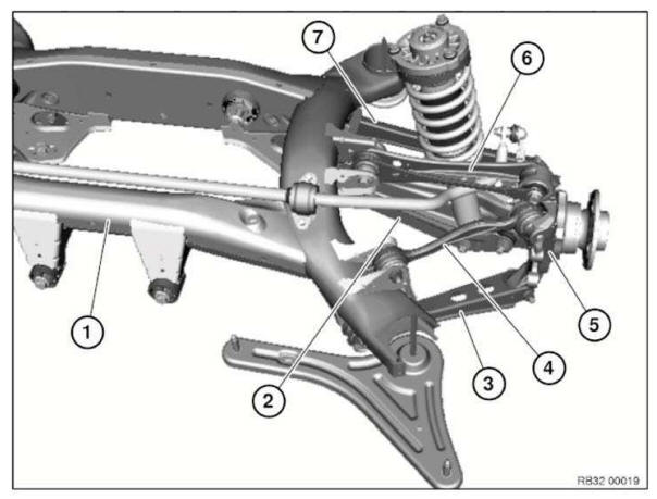
A WHEEL ALIGNMENT CHECK must be carried out after the following work:
- Release of following screw connections:
- Camber arm on rear axle support (2)
- Toe arm on rear axle support (7)
- Replacement of following parts:
- Rear axle support (1)
- Toe arm (2)
- Wheel carrier (5)
- Wishbone (6)
- Toe arm (7)
Risk of injury if oil comes into contact with eyes and skin
Danger of injury! Contact with eyes or skin may result in injury!
Possible symptoms are:
- Impaired sight
- Irritation of the eyes
- Reddening of the skin
- Rough and cracked skin
Protective measures/rules of conduct:
- Wear safety goggles
- Wear oil-resistant protective gloves
- Observe country-specific safety regulations
First aid measures:
- Eye contact: Rinse eyes immediately with plenty of water for at least 15 minutes; if available, use an eye-rinsing bottle. If irritation of the eyes persists, consult a doctor.
- Skin contact: Wash off with soap and water immediately. If irritation persists, consult a doctor.
NOTE: Do not use solvents/thinners.
Safety information for working on vehicles with automatic engine start-stop function (msa)
WARNING: If the engine hood/bonnet contact is pulled upwards (workshop mode), the information "switch closed" is output. The automatic engine start-stop function is active.
An automatic engine start is possible.
Observe safety precautions when working on MSA vehicles.
Before carrying out practical work on the engine, always ensure that the MSA functionality is deactivated so as to prevent automatic engine starting while work is being carried out in the engine compartment. MSA function is deactivated by:
- Deactivate MSA by means of button (1) in passenger compartment
- Open seat belt buckle and driver's door
Open engine bonnet/hood and ensure that engine hood/bonnet contact is not in workshop mode
- Workshop mode A = 10 mm
- Basic setting (engine hood/bonnet open) B = 7 mm
To make sure that the engine hood/bonnet contact is at the basic setting, if necessary press the hood/bonnet contact up to the limit position before starting work and slowly release.
Safety instructions for handling oil
WARNING: DANGER OF POISONING if oil is ingested/absorbed through the skin! RISK OF INJURY if oil comes into contact with eyes and skin!
Recycling: Observe country-specific waste disposal regulations.
Measures if oil is unintentionally released:
- Personal precautionary measures: Danger of slipping! Keep noninvolved persons away from the work area. Wear personal protective clothing/equipment.
- Environmental protection measures: Prevent oil from draining into drain channels, sewerage systems, pits, cellars, water and the ground.
- Limiting spread: Use oil blocks to prevent the surface spread of oil.
- Cleaning procedure: Bind and dispose of escaped oil with nonflammable absorbents.
NOTE: Do not flush oil away with water or aqueous cleaning agents.
START-UP OF ICM CONTROL UNIT
NOTE: Start-up of ICM control unit must be carried out:
- After replacement or removal and installation of ICM control unit
Connect vehicle to BMW diagnosis system.
Select and carry out start-up of ICM control unit under Service functions.
TEST CONDITIONS FOR CHASSIS/WHEEL ALIGNMENT CHECK
Observe the following test conditions prior to the chassis/wheel alignment check:
1. Only BMW approved wheel and tire combinations may be installed on the vehicle 2. Correct tread depth. The tread depth for each axle may differ from left to right by max. 1-2 mm.
3. Correct tire pressure (see label on vehicle).
4. All chassis and suspension components must be technically OK.
5. Condition of suspension and shock absorbers OK: Visually inspect for breakage, etc.
6. Vehicles with self-levelling suspension: Pull fuse of air supply system so that there is no controlling down or up.


Other materials:
BMW X3 (F25) Service & Repair Manual > Suspension: Pump and oil supply
INSTRUCTIONS FOR REMOVING AND INSTALLING EAR CLIPS
Special tools required:
32 1 260
NOTE: The work steps are show on assorted components.
Ear clip must always be replaced.
To remove an ear clip, place special tool 32 1 260 at right angles to ear and cut ear open.
The ear clip can be f ...
