BMW X3 (F25) Service & Repair Manual: Disc wheels (rims)
- Checking wheel rim for lateral and radial runout
- General information on light alloy disc wheels
- Initializing run flat indicator (rpa)
- Removing and installing rdc (tire pressure control) control unit (low cost)
- Removing and installing/replacing rdc wheel electronics (2nd generation/3rd generation)
Checking wheel rim for lateral and radial runout
Necessary preliminary tasks:
- Remove WHEEL.
- Check WHEEL for lateral and radial runout.
- Remove TIRE from disc wheel.
- Remove dirt from rim base and rim flange.
IMPORTANT: Disc wheels are not allowed to be repaired!
Mount disc wheel in balancing machine.
Use suitable wheel centering element supplied with corresponding balancing machine.
- Basic flange
- Wheel centering element
- Type flange
- Clamping nut
Place dial gauge sensor on rim shoulder.
Turn wheel by hand and measure max. radial runout .
NOTE: Dial gauge must be vertical to rim shoulder.
Position sensor on rim flange.
Turn wheel by hand and measure max. lateral runout .
Carry out measurement on both rim flanges.
NOTE: Dial gauge must be vertical to rim flange.
IMPORTANT: Avoid clamping errors during subsequent installation work.
General information on light alloy disc wheels
NOTE: It is sometimes difficult to distinguish light alloy disc wheels visually from steel disc wheels.
Identifying features:
- Sticker on light alloy disc wheel. (1) = Indication "Aluminum"
- Wall thickness of rim dish: approx. 8 mm.
- Light alloy disc wheels are not magnetic.
- Light alloy disc wheels can be identified from their BMW parts numbers.
IMPORTANT:
- Use only BMW-approved two-part balancing weights.
- When fitting two-part balancing weights, always use specified tools.
- Do not straighten light alloy disc wheels: always replace damaged light alloy disc wheels.
- Notches in light alloy disc wheels can lead to cracking.
- Do not lubricate wheel studs.
- When fitting tires, avoid damaging light alloy disc wheels, e.g. on sharp-edged retaining claws on tire fitting machine.
Initializing run flat indicator (rpa)
NOTE: Checking the tire pressure is based on speed monitoring of the wheels in relation to each other. A tire puncture is detected and signalled by way of a deviation in specific speed ratios.
The four tires mounted on the vehicle are monitored while the vehicle is driving.
Initialization must be carried out in each case immediately after tire pressures have been corrected, after tires/wheels have been exchanged and after repair work to the air spring system.
IMPORTANT: The Run Flat Indicator does not function when the vehicle is driven with the compact spare wheel.
RDC RESETTING
NOTE: RDC monitors the tire pressure in the four wheels.
Each tire incorporates an Wheel electronics module, which constantly monitors the tire pressure.
The system signals when the tire pressure drops in one or more tires.
Resetting must be carried out in each case immediately after tire pressures have been corrected, after tires/wheels have been replaced and after repairs to the air spring system.
Please refer to the relevant Owner's Handbook for details of the resetting procedure.
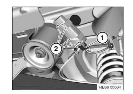
Removing and installing rdc (tire pressure control) control unit (low cost)
IMPORTANT: Read and comply with notes on PROTECTION AGAINST ELECTROSTATIC DAMAGE (ESD protection).
Disconnect plug connection (1).
Press retaining tabs (2) apart as indicated by arrow.
Pull out TPC control unit
Replacement:
- Carry out programming/encoding
Removing and installing/replacing rdc wheel electronics (2nd generation/3rd generation)
IMPORTANT: Before removing and installing, check which generation of RDC wheel electronics module is installed! If the wheel electronics have been removed, the complete valve must be replaced.
NOTE: There are two different wheel electronics. The SP303 wheel electronics module must be used with RDC-01 and RDC-02 from model year 03/06.
The Gen3 wheel electronics must be used with the RDC-LC from model year 09/2010 (all F0x/F1x vehicles).
If a tire sealant has been used, replace the wheel electronics.
When a tire has been removed, do not clean the rim with installed wheel electronics with high-pressure cleaning equipment.
Before the installation of new wheel electronics with valve, thoroughly clean the valve bore of the wheel rim.
Do not treat wheel electronics with solvents, cleaning agents etc. If dirt contamination, wipe with a clean cloth only.
Do not clean wheel electronics with compressed air.
Necessary preliminary tasks:
- REMOVE TIRE
Labelling of generation 2.3 wheel electronics
- Transmission frequency of wheel electronics
- Large Torx socket screw
- BMW part number
- Tightening torque of Torx screw and union nut
- Width across flats of union nut
- Serial number of wheel electronics
- Production date of wheel electronics
Labelling of generation 2.4 and 3.3 wheel electronics
- Data Matrixcode
- BMW part number
- FCC ID = radio authorization
- Wheel electronics ID
- Transmission frequency
- Pressure sensor
- Production date of wheel electronics
- Tightening torque
- Width across flats of union nut
Labelling of generation 3.4/3.41 wheel electronics
- FCC ID = radio authorization
- Tightening torque
- Pressure sensor
- Data Matrixcode
- Production date of wheel electronics
- Transmission frequency
- Wheel electronics ID
- Width across flats of union nut
- BMW part number
NOTE: The following illustrations only show removal and refitting of the 3rd generation wheel electronics module. The instructions also apply without alteration to the 2nd generation wheel electronics.
Removing wheel electronics
Release union nut (1).
Remove wheel electronics and valve (1) from valve hole.
Using suitable pliers (2), unscrew valve (1) from the thread of the square-head bolt (3), while holding the wheel electronics module (4) firm. Completely unscrew valve (1).
Remove square head screw from fixture for wheel electronics module.
Installation note:
The valve must be renewed! Failure to replace the part leads to leaks!
IMPORTANT: Before the installation of new wheel electronics with valve, thoroughly clean the valve bore of the wheel rim! Also make sure that the valve bore is free of burrs
Installing wheel electronics
Insert new square-head bolt (1) in wheel electronics module (2).
Screw single-use valve insert (3) three turns onto square-head bolt (1).
NOTE: Make sure the square bolt head (1) fits exactly in the fixture for the wheel electronics module!
Insert valve insert with wheel electronics into cleaned valve bore.
Both outer feet on the underside of the wheel electronics module must be resting against the rim wall.
Screw on union nut (1) by hand as far as it will go.
Tighten union nut until the inner strip-off ring breaks. Breakage is perceptible audibly and tangibly (momentary drop in torque resistance).
Then fully tighten union nut (1).
IMPORTANT: Fixing must not under any circumstances be retightened! The square-head bolt should be located precisely in the wheel electronics module fixture.
After tightening, the wheel electronics module must fit snugly on the wheel rim!
 Wheels
...
 Tires
Tires
...
Other materials:
BMW X3 (F25) Service & Repair Manual > Brakes: Accelerator pedal actuation
REMOVING AND INSTALLING OR REPLACING ACCELERATOR PEDAL MODULE
Take off cap.
Release screw.
Pull accelerator pedal module upwards out of fixture.
Pull off connector (1).
Remove accelerator pedal module.
IMPORTANT:
Accelerator pedal module can only be replaced completely with ...
