BMW X3 (F25) Service & Repair Manual: Transmission in general
- Danger of poisoning if oil is ingested/absorbed through the skin
- Checking/topping up oil level in automatic transmission (GA8HP45Z, GA8HP50Z, GA8HP90Z)
- Installing exchange transmission (GA8HP45Z) (N52, N55, N47)
- Installing exchange transmission (GA8HP45Z) (N20)
- Removing and installing automatic transmission (GA8HP45Z) (N20)
- Removing and installing automatic transmission (GA8HP45Z) (N47)
- Removing and installing automatic transmission (GA8HP45Z) (N52)
- Removing and installing automatic transmission (GA8HP45Z) (N55)
- Risk of injury if oil comes into contact with eyes and skin
- Safety instructions for handling oil
- Universal bmw transmission take-up
- Universal transmission retaining bridge
Danger of poisoning if oil is ingested/absorbed through the skin
Danger of poisoning! Ingesting oil or absorbing through the skin may cause poisoning! Possible symptoms are:
- Headaches
- Dizziness
- Stomach aches
- Vomiting
- Diarrhoea
- Cramps/fits
- Unconsciousness
Protective measures/rules of conduct:
- Pour oil only into appropriately marked containers
- Do not pour oil into drinking vessels (drinks bottles, glasses, cups or mugs)
- Observe country-specific safety regulations
First aid measures:
- Do not induce vomiting.
If the person affected is still conscious, he/she must rinse out their mouth with water, drink plenty of water and consult a doctor immediately.
If the person affected is unconscious, do not administer anything by mouth, place the person in the recovery position and seek immediate medical attention.
Checking/topping up oil level in automatic transmission (GA8HP45Z, GA8HP50Z, GA8HP90Z)
IMPORTANT:
- Do not let skin come in contact with transmission oil and do not inhale fuel vapors.
- Wear protective gloves.
- Ensure adequate ventilation
IMPORTANT: Use only the approved TRANSMISSION OIL .
To set the correct level, it is mandatory that the service function "Transmission control unit: oil adjustment" is performed using the diagnosis system.
Failure to comply with this requirement will result in serious damage to the automatic transmission. Conditions for the oil adjustment:
- Initial condition: Transmission oil temperature 30 º C to 40 ºC
- Final condition: Transmission oil temperature 40 º C to 50 ºC
IMPORTANT: Transmission GA8HP70Z with N57 engine from 03/2011!!
Precondition for oil adjustment
- Transmission oil temperature 30ºC to maximum 40ºC.
(The transmission oil temperature must be maintained. This will increase the oil quantity in the transmission.)
Performing oil-level adjustment:
An oil-level adjustment is necessary for certain fault code entries in the automatic transmission and after repair (e.g. mechatronic replacement, converter replacement, transmission replacement).
- Connect diagnosis and information system.
- Service function (transmission control unit: Oil adjustment) call up
- Carry out oil level check in accordance with instructions
Adding transmission oil:
Stand vehicle on a level surface and secure against rolling off.
Undo oil filler plug (1).
Add automatic transmission fluid according to instructions in the BMW diagnosis system.
Installation note:
Replace sealing ring/oil filler plug Tighten down oil filler plug using
- Hexagon socket wrench AF 8
- Torque wrench
- Socket AF 8
Installing exchange transmission (GA8HP45Z) (N52, N55, N47)
IMPORTANT:
- Do not let skin come in contact with transmission oil and do not inhale transmission oil vapors.
- Wear protective gloves.
- Ensure adequate ventilation
Drain automatic transmission fluid at oil drain plug.
IMPORTANT: After completion of work, program control transmission control unit.
Recycling:
Catch and dispose of escaping transmission oil.
Observe country-specific waste disposal regulations.
IMPORTANT:
- Before installing exchange transmission, always flush TRANSMISSION OIL COOLER TOGETHER WITH LINES .
- After completion of work, CHECK TRANSMISSION OIL LEVEL .
- Use only approved TRANSMISSION OIL .
Failure to comply with this requirement will result in serious damage to the automatic transmission Exchange transmissions come filled with oil
Necessary preliminary tasks:
- Remove automatic transmission .
- Remove transfer box .
Modify transportation retainers.
Convert all cable clips.
Convert all seal plugs.
Convert protective cap on output shaft.
IMPORTANT: After removing transportation retainer, secure torque converter against slipping out.
Transmission identification:
- On type plate
Installing exchange transmission (GA8HP45Z) (N20)
IMPORTANT:
- Do not let skin come in contact with transmission oil and do not inhale fuel vapors.
- Wear protective gloves.
- Ensure adequate ventilation.
Drain automatic transmission fluid at oil drain plug.
IMPORTANT: After completion of work, program control transmission control unit.
Recycling:
Catch and dispose of escaping transmission oil.
Observe country-specific waste disposal regulations.
IMPORTANT:
- Before installing exchange transmission, always flush TRANSMISSION OIL COOLER TOGETHER WITH LINES .
- After completion of work, CHECK TRANSMISSION OIL LEVEL .
- Use only approved TRANSMISSION OIL .
Failure to comply with this requirement will result in serious damage to the automatic transmission Exchange transmissions come filled with oil
Necessary preliminary tasks:
- Remove AUTOMATIC TRANSMISSION.
- Modify TRANSFER CASE .
Modify transportation retainers.
Convert all cable clips.
Convert all seal plugs.
Convert protective cap on output shaft.
IMPORTANT: After removing transportation retainer, secure torque converter against slipping out.
Transmission identification:
- On type plate
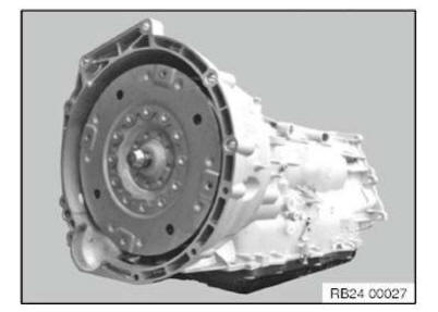
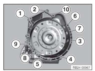
OVERVIEW OF TRANSMISSION HOUSING (GA8HP45Z)
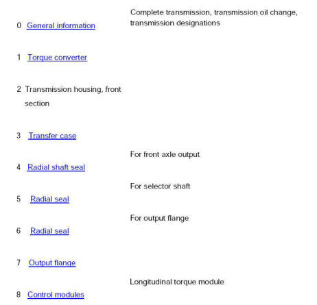
Complete transmission, transmission oil change, transmission designations
Removing and installing automatic transmission (GA8HP45Z) (N20)
Special tools required:
- 2 222 741
- 24 2 390
- 23 4 050
- 00 2 030
IMPORTANT: To prevent heavy damage to the engine block, the protruding thread of the transmission bolts absolutely must be checked for damage and corrosion before removal. If there are signs of corrosion, the rust must be removed and the threads must be cleaned before removal. Replace rusted, damaged screws.
Failure to comply with this instruction will result in serious damage to the engine block and transmission.
IMPORTANT: After completion of repair work, check TRANSMISSION OIL LEVEL .
Use only the approved TRANSMISSION OIL .
Failure to comply with this requirement will result in serious damage to the automatic transmission!
Necessary preliminary tasks:
- Clamp off BATTERY .
- Remove underbody protection .
- Remove REINFORCEMENT PLATE .
Important notes on installation are described in this work step.
- Remove EXHAUST SYSTEM .
- Remove front PROPELLER SHAFT .
- Disconnect PROPELLER SHAFT at transmission, release center mount.
- Note:
- Bending the propeller shaft by an excessive angle can cause premature damage to the joint/propeller shaft!
- Tie up the propeller shaft to the vehicle underbody.
- Support engine with lifter when removing transmission.
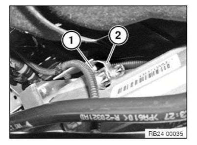
Release screw (1).
Remove holder (2).
Release screws (1).
Remove the protective plate (2).
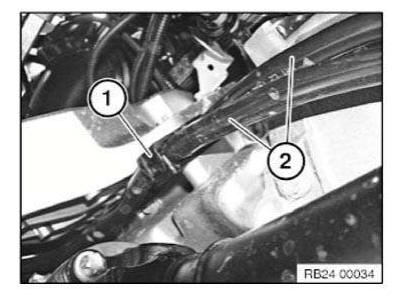
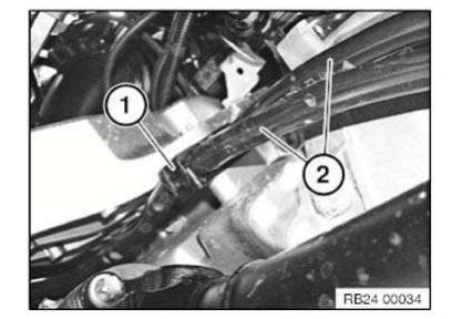
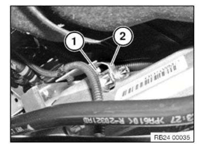
Release screw (1).
Disconnect hydraulic lines (2) to transmission oil cooler.
Installation note: Replace sealing rings.
Unscrew nuts (1).
Unfasten screws (2).
Remove bracket (3) and catalytic converter (5).
Unscrew nuts (4).
Remove rubber mounts for catalytic converter.
Release screws (1).
Remove cover plate (2) downwards.
Remove cover.
Crank engine at vibration damper in direction of rotation until screw (1) is visible in recess.
Undo all 6 bolts on torque converter.
IMPORTANT: Replace all 6 bolts on torque converter.
Unscrew knurled screw (1) from special tool 2 222 741 (do not remove completely) before inserting in the recess of the transmission housing.
Insert special tool 2 222 741 and shaped element (3) in the recess.
Slightly tighten knurled nut (2).
Screw in knurled screw (1) fully.
- Locating pin (4) must be located between converter and engine.
Move special tool 2 222 741 in the recess until the locating pin (4) rests against the converter.
Use knurled nut (2) to fix special tool 2 222 741 and converter in position.
- Unlock and disconnect connector (1) by turning.
- Do not touch pins.
- Release cable from brackets.
- Insert special tool 24 2 390 in sealing cup.
Tasks are described in Gearbox holder.
NOTES ON MECHATRONICS
IMPORTANT: Read and comply with important note.
Supporting transmission:
Support transmission with special tools 23 4 050 , 00 2 030 .
Secure transmission to mounting with tensioning strap (1).
Tasks are described in TRANSMISSION BRACKET.
Release screws.
Remove cross member.

Unplug connector (1) from transfer box control unit (longitudinal torque module).
Release screw (2).
Remove earth strap (3).
Release screws.
Installation note:
Check that fitting sleeves (1) are correctly seated.
Replace damaged fitting sleeves.
Installation note:
Twist torque converter until bore hole in torque converter is flush with bore hole of flywheel.
Flange automatic transmission to engine.
Removing and installing automatic transmission (GA8HP45Z) (N47)
Special tools required:
- 24 4 161
- 24 4 166
- 24 4 160
- 24 2 390
- 23 4 050
- 00 2 030
- 11 6 480
- 24 1 110
IMPORTANT: To prevent heavy damage to the engine block, the protruding thread of the transmission bolts absolutely must be checked for damage and corrosion before removal. If there are signs of corrosion, the rust must be removed and the threads must be cleaned before removal. Replace rusted, damaged screws.
Failure to comply with this instruction will result in serious damage to the engine block and transmission.
IMPORTANT: After completion of repair work, check TRANSMISSION OIL LEVEL .
Use only the approved TRANSMISSION OIL .
Failure to comply with this requirement will result in serious damage to the automatic transmission!
Necessary preliminary tasks:
- Disconnect the BATTERY
- Remove underbody protection
- Remove REINFORCEMENT PLATE.
Important installation notes are described in this job item
- Remove EXHAUST SYSTEM
- Remove heat shields
- REMOVE STARTER MOTOR
- Remove PROPELLER SHAFT FROM FRONT AXLE DIFFERENTIAL
- Detach PROPELLER SHAFT at gearbox, release center bearing
- Note:
- Bending the propeller shaft by an excessive angle can cause premature damage to the joint/propeller shaft!
- Tie up propeller shaft to underbody.
- Support engine with jack when removing gearbox
Release screw (1).
Disconnect hydraulic lines (2) to transmission oil cooler.
Installation note: Replace sealing rings.
Detach cable holder (1) from gearbox.
Unfasten screws (2).
Unscrew nuts (3).
Remove holder (4).
Prepare special tool (1) 24 4 161 (A) with shaped element (2) 24 4 166 as pictured.
Insert special tool 24 4 160 into recess of transmission housing and clamp gently with screw (1).
Raise by turning screw (2) and clamp down.
Then tighten down screw (1).
- Unlock and disconnect connector (1) by turning.
- Do not touch pins.
- Release cable from brackets.
- Insert special tool 24 2 390 in sealing cup.
Tasks are described in Gearbox holder.
NOTES ON MECHATRONICS
IMPORTANT: Read and comply with important note.
Supporting transmission:
Support transmission with special tools 23 4 050 , 00 2 030 .
Secure transmission to mounting with tensioning strap (1).
Tasks are described in TRANSMISSION BRACKET.
After completion of work, check transmission fluid level.
Release screws.
Remove cross member.
Unplug connector (1) from transfer box control unit (longitudinal torque module).
Release screw (2).
Remove earth strap (3).
Crank engine with special tool 11 6 480 at the vibration damper in direction of rotation until screw (1) is visible in the recess.
Release all 4 bolts of torque converter with special tool 24 1 110 .
Installation note: Replace converter screws. Remove any remaining adhesive residue from the thread.
Release bolts and remove transmission.
NOTE: Graphic similar
Installation note:
Bore hole (1) of driving plate must be accessible from recess on engine oil sump. Check that fitting sleeves (2...3) are correctly seated.
Replace damaged fitting sleeves.
Installation note:
Rotate torque converter until bore hole in torque converter is flush with bore hole in drive plate.
Flange automatic transmission to engine.
Removing and installing automatic transmission (GA8HP45Z) (N52)
Special tools required:
- 24 4 161
- 24 4 166
- 24 4 160
- 24 2 390
- 23 4 050
- 00 2 030
- 24 1 110
IMPORTANT: To prevent heavy damage to the engine block, the protruding thread of the transmission bolts absolutely must be checked for damage and corrosion before removal. If there are signs of corrosion, the rust must be removed and the threads must be cleaned before removal. Replace rusted, damaged screws.
Failure to comply with this instruction will result in serious damage to the engine block and transmission.
IMPORTANT: After completion of repair work, check TRANSMISSION OIL LEVEL .
Use only the approved TRANSMISSION OIL .
Failure to comply with this requirement will result in serious damage to the automatic transmission! IMPORTANT: Aluminium screws/bolts must be replaced each time they are released. Aluminium screws/bolts are permitted with and without color coding (blue).
For reliable identification: Aluminium screws/bolts are not magnetic. Jointing torque and angle of rotation must be observed without fail (risk of damage).
Necessary preliminary tasks:
- Disconnect the BATTERY
- Remove FAN COWL
- Remove underbody protection
- Remove REINFORCEMENT PLATE.
Important installation notes are described in this job item
- Remove EXHAUST SYSTEM
- Remove heat shields
- Remove PROPELLER SHAFT FROM FRONT AXLE DIFFERENTIAL
- Detach PROPELLER SHAFT at gearbox, release center bearing
- Tie up propeller shaft to underbody.
- Note:
- Bending the propeller shaft by an excessive angle can cause premature damage to the joint/propeller shaft!
- Support engine with jack when removing gearbox
Disconnect connectors (1) and (2) from bracket (3) and detach.
Release screw (1).
Disconnect hydraulic lines (2) to transmission oil cooler.
Installation note: Replace sealing rings.
Release holder (1).
Detach hydraulic lines (2) from bracket (1).
Release screws (1).
Slacken nut (2).
Remove bracket (3).
Remove holder (1).
Release screws (1).
Remove holder (2).
Remove heat shield (3).
Prepare special tool (1) 24 4 161 (A) with shaped element (2) 24 4 166 as pictured.
Insert special tool 24 4 160 into recess of transmission housing and clamp gently with screw (1).
Raise by turning screw (2) and clamp down.
Then tighten down screw (1).
- Unlock and disconnect connector (1) by turning.
- Do not touch pins.
- Release cable from brackets.
- Insert special tool 24 2 390 in sealing cup.
Tasks are described in Gearbox holder.
NOTES ON MECHATRONICS
IMPORTANT: Read and comply with important note.
Supporting transmission:
Support transmission with special tools 23 4 050 , 00 2 030 .
Secure transmission to mounting with tensioning strap (1).
Tasks are described in TRANSMISSION BRACKET.
After completion of work, check transmission fluid level.
Release screws.
Remove cross member.
Unplug connector (1) from transfer box control unit (longitudinal torque module).
Release screw (2).
Remove earth strap (3).
Crank engine at vibration damper in direction of rotation until screw (1) is visible in recess.
Release all 6 bolts of torque converter with special tool 24 1 110 .
Installation note: Replace converter screws. Remove any remaining adhesive residue from the thread.
Note installed position of brackets (1 and 2) when removing gearbox.
Release screws.
Installation note:
Observe screw fastening sequence without fail.
Aluminium screws must be replaced.
Tightening torque and angle of rotation Aluminium screws 24 00 2AZ (6, 7, 8, 9)
Installation note:
Bore hole (1) of driving plate must be accessible from recess on engine oil sump. Check that fitting sleeves (2...3) are correctly seated.
Replace damaged fitting sleeves.
Installation note:
Rotate torque converter until bore hole in torque converter is flush with bore hole in drive plate.
Flange automatic transmission to engine.
Removing and installing automatic transmission (GA8HP45Z) (N55)
Special tools required:
- 24 4 161
- 24 4 166
- 24 4 160
- 24 2 390
- 23 4 050
- 00 2 030
- 24 1 110
IMPORTANT: To prevent heavy damage to the engine block, the protruding thread of the transmission bolts absolutely must be checked for damage and corrosion before removal. If there are signs of corrosion, the rust must be removed and the threads must be cleaned before removal. Replace rusted, damaged screws.
Failure to comply with this instruction will result in serious damage to the engine block and transmission.
IMPORTANT: After completion of repair work, check TRANSMISSION OIL LEVEL .
Use only the approved TRANSMISSION OIL .
Failure to comply with this requirement will result in serious damage to the automatic transmission! IMPORTANT: For vehicles with N54/N55 engine up to production date 09/2012, aluminum bolts for the for the securing of the transmission are also installed.
As of production date 09/2012, only steel bolts are installed for the securing of the transmission.
NOTE: Aluminium screws/bolts must be replaced each time they are released .
Aluminium screws/bolts are permitted with and without color coding (blue).
For reliable identification: Aluminium screws/bolts are not magnetic.
Jointing torque and angle of rotation must be observed without fail (risk of damage) .
The aluminum bolts can be optionally replaced by steel bolts.
Necessary preliminary tasks:
- Disconnect the BATTERY
- Remove FAN COWL
- Remove underbody protection
- Remove REINFORCEMENT PLATE.
Important installation notes are described in this job item
- Release hose socket from charge air cooler on left and right.
- Remove EXHAUST SYSTEM
- Remove heat shields
- Remove PROPELLER SHAFT FROM FRONT AXLE DIFFERENTIAL
- Detach PROPELLER SHAFT at gearbox, release center bearing
- Tie up propeller shaft to underbody.
- Note:
- Bending the propeller shaft by an excessive angle can cause premature damage to the joint/propeller shaft!
- Support engine with jack when removing gearbox
Remove upper part of cable duct (1).
Release screw (1).
Disconnect hydraulic lines (2) to transmission oil cooler.
Installation note: Replace sealing rings.
Release holder (1).
Detach hydraulic lines (2) from bracket (1).
Release screws (1).
Slacken nut (2).
Remove bracket (3).
Release screws (1).
Remove holder (2).
Remove heat shield (3).
Prepare special tool (1) 24 4 161 (A) with shaped element (2) 24 4 166 as pictured.
Insert special tool 24 4 160 into recess of transmission housing and clamp gently with screw (1).
Raise by turning screw (2) and clamp down.
Then tighten down screw (1).
- Unlock and disconnect connector (1) by turning.
- Do not touch pins.
- Release cable from brackets.
- Insert special tool 24 2 390 in sealing cup.
Tasks are described in Gearbox holder.
NOTES ON MECHATRONICS
IMPORTANT: Read and comply with important note.
Supporting transmission:
Support transmission with special tools 23 4 050 , 00 2 030 .
Secure transmission to mounting with tensioning strap (1).
Tasks are described in TRANSMISSION BRACKET.
After completion of work, check transmission fluid level.
Release screws.
Remove cross member.
Unplug connector (1) from transfer box control unit (longitudinal torque module).
Release screw (2).
Remove earth strap (3).
Crank engine at vibration damper in direction of rotation until screw (1) is visible in recess.
Release all 6 bolts of torque converter with special tool 24 1 110 .
Installation note: Replace converter screws. Remove any remaining adhesive residue from the thread.
Note installed position of brackets (1 and 2) when removing gearbox.
Release screws.
Installation note:
Observe screw fastening sequence without fail.
Aluminium screws must be replaced.
Tightening torque and angle of rotation Aluminium screws 24 00 2AZ (7, 8, 9, 10, 11)
Installation note:
Bore hole (1) of driving plate must be accessible from recess on engine oil sump. Check that fitting sleeves (2...3) are correctly seated.
Replace damaged fitting sleeves.
NOTE: Similar to graphic.
Installation note:
Rotate torque converter until bore hole in torque converter is flush with bore hole in drive plate.
Flange automatic transmission to engine.
Risk of injury if oil comes into contact with eyes and skin
Danger of injury! Contact with eyes or skin may result in injury! Possible symptoms are:
- Impaired sight
- Irritation of the eyes
- Reddening of the skin
- Rough and cracked skin
Protective measures/rules of conduct:
- Wear safety goggles
- Wear oil-resistant protective gloves
- Observe country-specific safety regulations
First aid measures:
- Eye contact: Rinse eyes immediately with plenty of water for at least 15 minutes; if available, use an eye-rinsing bottle. If irritation of the eyes persists, consult a doctor.
- Skin contact: Wash off with soap and water immediately. If irritation persists, consult a doctor.
NOTE: Do not use solvents/thinners.
Safety instructions for handling oil
WARNING: DANGER OF POISONING if oil is ingested/absorbed through the skin! RISK OF INJURY if oil comes into contact with eyes and skin!
Recycling: Observe country-specific waste disposal regulations.
Measures if oil is unintentionally released:
- Personal precautionary measures: Danger of slipping! Keep noninvolved persons away from the work area. Wear personal protective clothing/equipment.
- Environmental protection measures: Prevent oil from draining into drain channels, sewerage systems, pits, cellars, water and the ground.
- Limiting spread: Use oil blocks to prevent the surface spread of oil.
- Cleaning procedure: Bind and dispose of escaped oil with nonflammable absorbents.
NOTE: Do not flush oil away with water or aqueous cleaning agents.
TRANSMISSION DESIGNATIONS
Breakdown of BMW designation:
Manual gearbox:
Automatic transmission:
Universal bmw transmission take-up
Special tools required:
- 00 2 030
- 23 4 050
NOTE:
- The universal transmission bracket is introduced for the E60 AWD
- Suitable for manual and automatic transmissions
IMPORTANT: Front and rear supports (1) can be laterally adjusted by means of screws (2).
Carrier (3) of rear supports (1) can be longitudinally adjusted by means of screw.
Supports must be adapted in length and width to the transmission.
Supporting transmission:
Support transmission with special tools 23 4 050 , 00 2 030 .
IMPORTANT: Transmission must be secured with tensioning strap (1).
Universal transmission retaining bridge
Special tools required:
- 00 1 450
- 24 0 200
NOTE: The transmission retaining bridge 24 0 200 is suitable for both manual and automatic transmissions
IMPORTANT: Adapters and spindles must be adapted for positive locking to the transmission.
(Risk of injury)
Adapt adapters (1) and spindle with thrust piece (3) to transmission.
Adapt length with slide (2).
Screw in spindle (4).
IMPORTANT: Before mounting on assembly stand 00 1 450, check retaining bridge for secure seating.

 Transmission case, oil sump
REMOVING AND INSTALLING/SEALING OR REPLACING TRANSMISSION OIL SUMP
(GA8HP45Z)
IMPORTANT:
Do not let skin come in contact with tra ...
Other materials:
BMW X3 (F25) Service & Repair Manual > DTC: Brake pad replacement reminder
NOTE: To determine the appropriate reset procedure, refer to BRAKE PAD
REPLACEMENT REMINDER RESET INDEX. Only vehicles listed in this index
have a specific brake pad warning light reset procedure. For other vehicles,
perform PROCEDURE 1 first. If light does not reset, perform PROCEDURE 2. If
the ...
