BMW X3 (F25) Service & Repair Manual: Wheel wells
- Replace front right wheel arch
- Replacing engine support/front left side frame connection (front left wheel arch removed)
- Replacing front left wheel arch
- Replacing rear left outer wheel arch section (rear side panel removed)
- Replacing rear left outer wheel arch section with reinforcement (rear side panel removed)
- Stripping operations - replacing front left wheel arch
- Stripping operations - replacing front right wheel arch
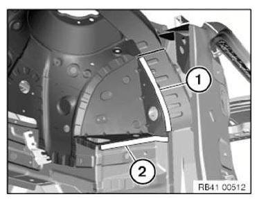
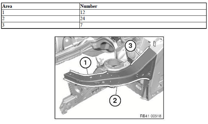
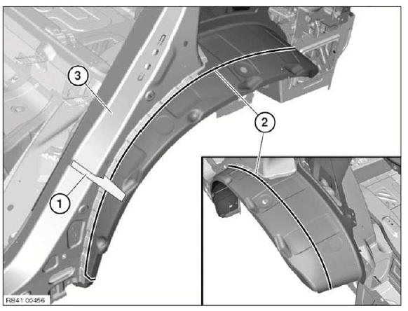
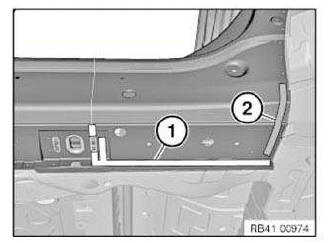
Replace front right wheel arch
Note the special vehicle identification number procedure when replacing the wheel arch (order the new body part with the vehicle identification number, if necessary)!
STRIP DOWN vehicle.
Read about the procedure in repair instructions for WHEEL ARCH FRONT LEFT and transfer schematically to the right side of the vehicle.
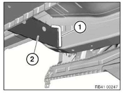
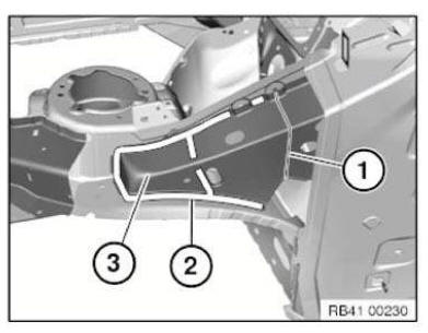
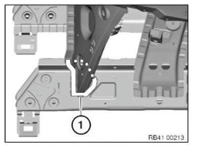
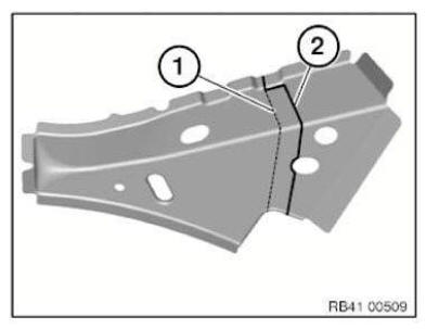
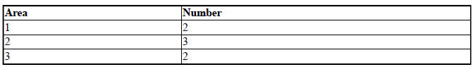
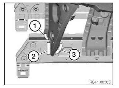
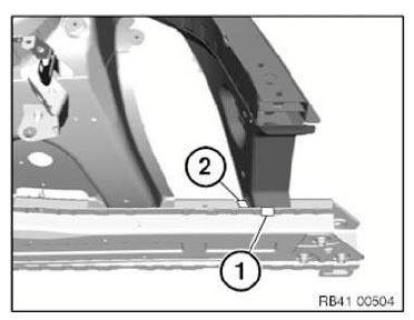
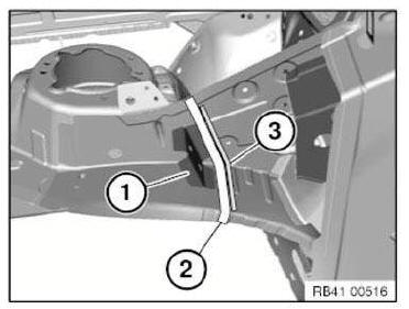
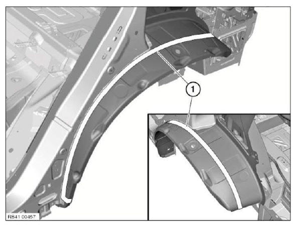
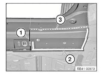
Deviating from the left side of the vehicle: Due to the ground connection (1), the new part will be welded in area (2).
Analogue to the left side of the vehicle: In areas (3) and (4) set 7 bore holes with a diameter of 4.2 mm for blind rivets N3.
Replacing engine support/front left side frame connection (front left wheel arch removed)
Observe procedure for REPAIR STAGE 3.
Read contents of BODY, GENERAL.
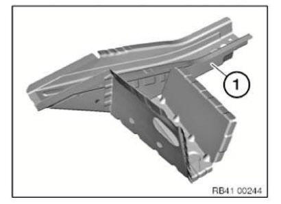
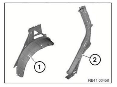
Following new body parts are required:
- (1) Engine support, rear
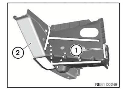
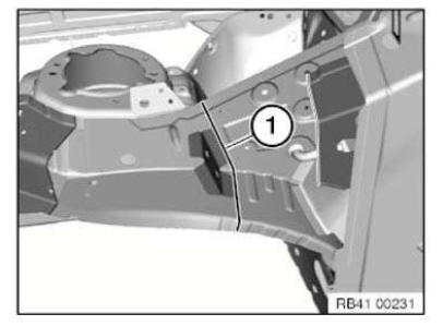
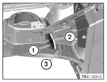
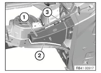
Removing the engine support side frame connection: Open welded connections in areas (1).
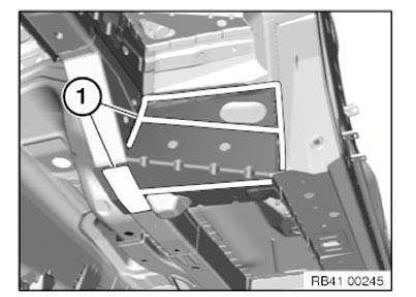
Open welded connections in areas (1).
Remove engine support/side frame (2).

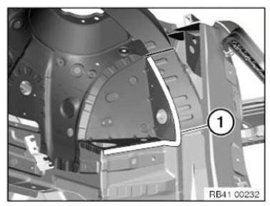
Open welded connections in areas (1).
Remove reinforcement (2).
New part preparation
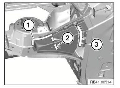
Open welded connections in areas (1).
Remove engine support (2).
Installing the engine support side frame connection
Install and weld new parts.
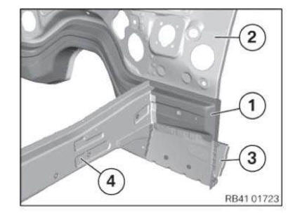
NOTE: First, the reinforcement of the engine support side frame connection must be installed and welded for reasons of accessibility as a separate component.
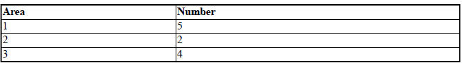
NOTE: The bulkhead cross member (1) is filled with low-flammable cavity foam.
In case of smoke formation, stop the welding procedure and cool the welded area with compressed air if applicable.
- (2) Bulkhead
- (3) Connection engine support side frame
- (4) Engine support
REPLACING ENGINE SUPPORT/FRONT RIGHT SIDE FRAME CONNECTION (FRONT RIGHT WHEEL ARCH REMOVED)
The work is identical to replacing the "ENGINE SUPPORT FRONT LEFT SIDE FRAME CONNECTION".
Replacing front left wheel arch
Follow procedure for REPAIR STAGE 3.
Read contents of BODY, GENERAL.
STRIP DOWN vehicle.
Use only approved SPOT-WELDING APPARATUS for repairs.
Place vehicle on straightening bench.
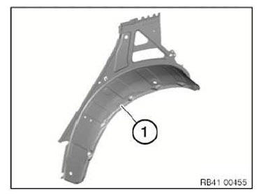
Following new body parts are required :
- (1) Wheel arch, front
- (2) Outer wheel arch carrier support
- (3) Carrier support end plate
- (4) A-pillar bulkhead
- (5) Shaped part, wheel arch carrier support (not shown)
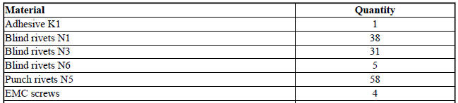
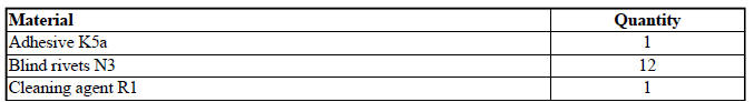
Following consumables are required:

Removing the wheel arch
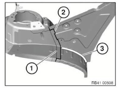
Mark severance cut (1) as pictured and cut.
OPEN spot-welded adhesive joints in area (2).
Open welded connections in area (3).
Release metal section from cavity sealing (4) and remove.
NOTE: Separating cut (1) is only required for removal.

Mark severance cut (1) as pictured and cut.
Open welded connections in areas (2).
Remove carrier support end plate metal section (3).
Mark severance cut (1) directly next to bulkhead component edge and cut.
Open welded connections in area (1).
Open welded connections in areas (1).
Open welded connections in area (1).
Open welded connections in areas (1).
Remove the wheel arch.
New part preparation
Release the applicable welded connections and separate the engine support from the wheel arch.
NOTE: Welded connections must be detached from side of engine support!
Mark new part in accordance with severance cut on vehicle (1) + 20 mm extra material and cut (2).
Open welded connections in area (3) and remove wheel arch part section.
NOTE: New part is installed and welded overlapping in area of severance cut.
Mark new part in accordance with severance cut on vehicle (1) + 20 mm extra material and cut (2).
NOTE: New part is joined in area of overlap using adhesive riveting technology.
Adjust new part wheel arch in combination with wheel arch carrier support to fit with alignment bracket or universal mount and secure.
In areas (1) to (3), set dia. 6.8 mm bore holes for blind rivets N1.
In areas (1), create 4 dia. 6.8 mm bore holes for blind rivets N1.
In area (2) set 5 dia. 4.2 mm bore holes for blind rivets N3.
In areas (1) to (3), set dia. 6.8 mm bore holes for blind rivets N1.
In areas (1) and (2), set dia. 6.8 mm bore holes for blind rivets N1.
In area (1) set 5 dia. 4.2 mm bore holes for blind rivets N3.
In area (2) set 5 dia. 6.8 mm bore holes for blind rivets N1.
Remove carrier support new part.
Adjust A-pillar bulkhead new part (1) and secure.
Prepare wheel arch in area of overlap (3) for joining by welding.
NOTE: Bulkhead is welded for installation in area (2).
Adjust carrier support end plate new part (1) and secure.
In areas (1) to (3), set dia. 4.2 mm bore holes for blind rivets N3.
Adjust wheel arch carrier support new part to fit with alignment bracket or universal mount and secure.
In areas (1) and (3), set dia. 4.2 mm bore holes for blind rivets N3 .
In area (2) set bore holes dia. 4.2 mm for blind rivets N6 .


Remove new parts and deburr bore holes.
IMPORTANT: Structure bonding! OBSERVE preparation of bonding surfaces.
Installation of wheel arch with bulkhead
Clean bonding surfaces with cleaning agent R1.
Apply adhesive to bonding surfaces.
Adjust wheel arch to fit with alignment bracket or universal mount and secure.
NOTE: Use wheel arch carrier support to adjust wheel arch.
But do not yet rivet wheel arch carrier support! Rivet wheel arch with blind rivets.
Remove wheel arch carrier support.
Adjust bulkhead new part A-pillar (1) and weld.
Weld wheel arch in area (2).
Set additional 15-mm long metal active gas weld seams at a distance of 20 mm to component edge (3).
Installation of end plate carrier support
Clean bonding surfaces with cleaning agent R1.
Apply adhesive to bonding surfaces.
Adjust end plate carrier support (1) and rivet with blind rivets.
Use N5 punch rivets in areas (2) and (3).
Installation of wheel arch carrier support
Clean bonding surfaces with cleaning agent R1.
Apply adhesive to bonding surfaces.
Apply sealant to new CAVITY SEALING of wheel arch carrier support.
Adjust wheel arch carrier support new part to fit with alignment bracket or universal mount and rivet with blind rivets.
Use N5 punch rivets in areas (1) to (3).
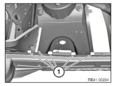
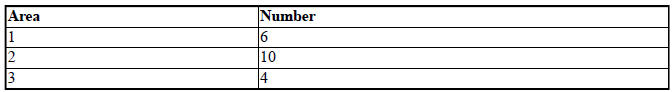
After adhesive has hardened, install one EMC screw in each case in areas (1).
In area (1) install one EMC screw.
Replacing rear left outer wheel arch section (rear side panel removed)
Read contents of BODY, GENERAL.
Observe procedure for (REPAIR STAGE 2)! Following new body parts are required :
- (1) Outer wheel arch section, rear
- (2) Shaped part, wheel arch, outer (not shown)
Following CONSUMABLES are required:

Removal of outer wheel arch section
Remove cavity sealing (1).
Mark severance cut (2) at component edge of C-pillar reinforcement (3) and cut.
Remove part of the outer wheel arch section.
Preparation of new part: Mark new part in accordance with severance cut on vehicle + 20 mm extra material and cut.
Adjust new parts in combination with side wall to fit and secure.
In area of bonding surface (1), drill 12 Ø 4.2 mm holes for blind rivets.
Installation of outer wheel arch section
IMPORTANT: Do not grind/sand new part in area of bonding surfaces.
Clean all bonding surfaces on new part and on vehicle with cleaning agent R1.
Apply adhesive to bonding surfaces.
Apply sealant to new CAVITY ACOUSTIC BAFFLE.
Install and rivet outer wheel arch section.
Replacing rear left outer wheel arch section with reinforcement (rear side panel removed)
Follow procedure for REPAIR STAGE 3.
Read contents of BODY, GENERAL.
Spot-weld bonding is used on this vehicle. Observe specific procedure .
Use only approved SPOT-WELDING APPARATUS for repairs.
Following new body parts are required :
- (1) Wheel arch, rear, outer half
- (2) C-pillar reinforcement
- (3) Shaped part, wheel arch, outer (not shown)
- (4) Shaped part, wheel arch, inner (not shown)
Removal of the outer wheel arch section with reinforcement
Additionally removing the side wall in the side sill area: Extend severance cut (1) to lower edge of entrance.
Open weld joints in area (2) and remove entrance section.
(3) = Severance cut progression for replacement of side wall.
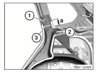
Mark severance cut (1) in accordance with dimension and cut.
IMPORTANT: Cut outer panel only.
Dimension a = approx. 70 mm.
Open welded connections in areas (2).
Remove cavity acoustic baffle (3).
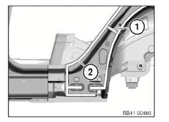
Remove cavity sealing (1).
Open welded connections in areas (2).
Remove reinforcement on C-pillar.
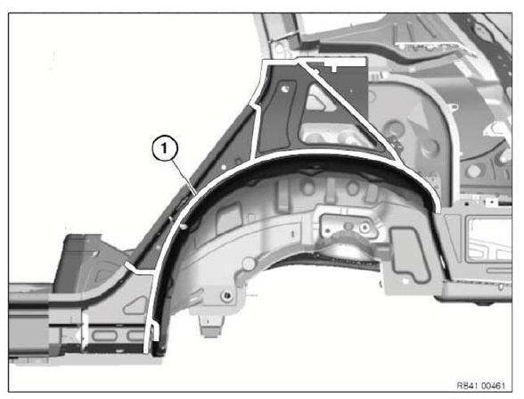
Open welded connections in area (1). Remove outer section of wheel arch.
New part preparation
Tear and separate the separating cut on the C-pillar reinforcement new part according to the vehicle.
Prepare REINFORCEMENT PLATE at severance cut.
Adjust new parts in conjunction with side panel to fit.
Installation of the outer wheel arch section with reinforcement
Apply sealant to new CAVITY SEALINGS.
Install new parts and reinforcement plate and weld in place.
Installation of additional side wall section in side sill area: Weld additional section in area (1).
Join additional section similarly to side wall using bonding/riveting technology in area (2).
Install 3 punch rivets N4 in area (2).
IMPORTANT: Risk of damage to adjoining adhesive areas! Avoid excessive application of heat.
Stripping operations - replacing front left wheel arch
NOTE: Owing to the different engine variants and equipment specifications, not all the components are taken into consideration.
The following list basically represents the removal sequence.
- Disconnect negative battery cable
- Remove bumper trim
- Remove front underbody protection assembly
- Remove front panel
- Remove front side panel left
- Remove trailing link on left spring strut dome
- Remove intake silencer housing
- Remove coolant expansion tank
- Remove front wheel arch cover (front section)
- Remove front wheel arch cover (rear section)
- Remove engine compartment lid
- Remove left engine compartment lid hinge
- Remove left partition wall for units compartment
- Remove brake booster
- Remove trailing link
- Remove left wishbone
- Remove spring strut with swivel bearing
- Release left wiring harness
Stripping operations - replacing front right wheel arch
NOTE: Owing to the different engine variants and equipment specifications, not all the components are taken into consideration.
The following list basically represents the removal sequence.
- Disconnect negative battery cable
- Remove bumper trim
- Remove front underbody protection assembly
- Remove front panel
- Remove front right side wall
- Remove DSC hydraulic unit
- Remove front wheel arch cover (front section)
- Remove front wheel arch cover (rear section)
- Remove engine compartment lid
- Remove right engine compartment lid hinge
- Remove right partition wall for units compartment
- Remove trailing link on right spring strut dome
- Remove microfilter housing
- Release right wiring harness
- Remove trailing link
- Remove right wishbone
- Remove spring strut with swivel bearing


Other materials:
BMW X3 (F25) Service & Repair Manual > Suspension: Pump and oil supply
INSTRUCTIONS FOR REMOVING AND INSTALLING EAR CLIPS
Special tools required:
32 1 260
NOTE: The work steps are show on assorted components.
Ear clip must always be replaced.
To remove an ear clip, place special tool 32 1 260 at right angles to ear and cut ear open.
The ear clip can be f ...
