BMW X3 (F25) Service & Repair Manual: Side frame and door pillars
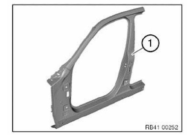
- Replace A-pillar, outer left
- Replace B-pillar with reinforcement on left
- Replace B-pillar, outer left
- Replacing A-pillar with reinforcement on left
- Replacing A-pillar with reinforcement on the left (with side member attachment)
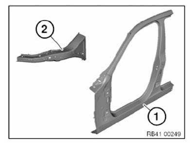
Replace A-pillar, outer left
Procedure OBSERVE repair stage 3! Read contents of BODY, GENERAL.
Spot-weld bonding is used on this vehicle. Observe specific PROCEDURE.
Use only approved SPOT-WELDING APPARATUS for repairs.
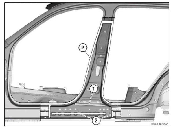
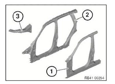
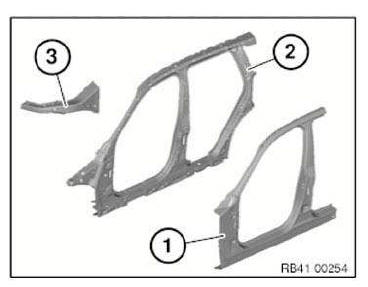
Following new body parts are required :
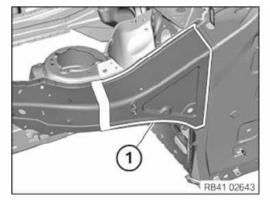
- (1) A-pillar with entrance
- (2) Carrier support, outside
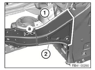
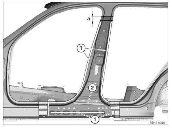
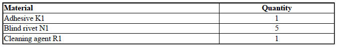
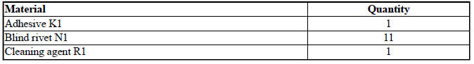
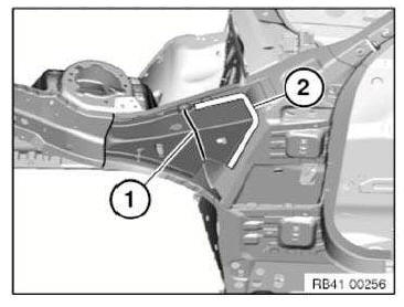
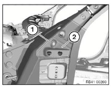
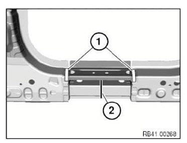
Removal: Mark severance cut in accordance with dimension and cut.
IMPORTANT: Cut outer panel only.
Dimension a = approx. 100 mm from 6 mm diameter hole.
LOOSEN spot-welded adhesive joints in area (1).
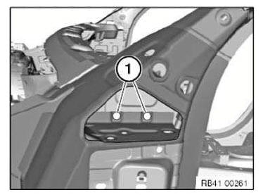
Open welded connections in area (2).
Remove partial section of carrier support.
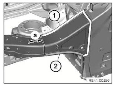
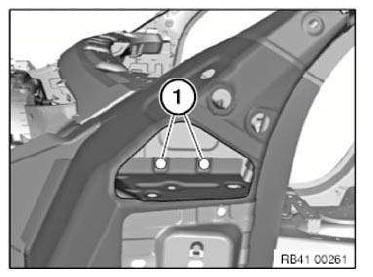
Mark severance cuts in accordance with specified dimensions and cut.
IMPORTANT: Cut outer panel only for following severance cuts.
Dimension a = approx. 600 mm from 20 mm diameter hole.
Dimension b = approx. 450 mm from roof edge.
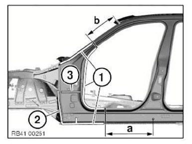
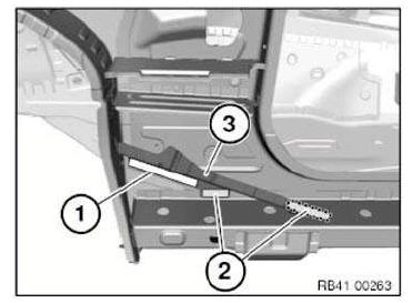
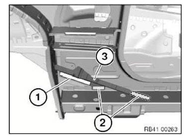
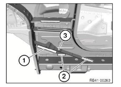
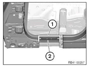
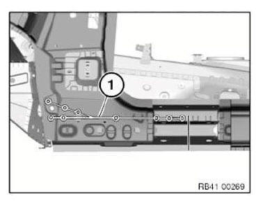
Open welded connections in areas (1).
Open spot-welded adhesive joints in area (2) Release and remove A-pillar from cavity sealing (3).
Preparation of new part: Mark severance cuts on new parts according to severance cuts on vehicle and sever.
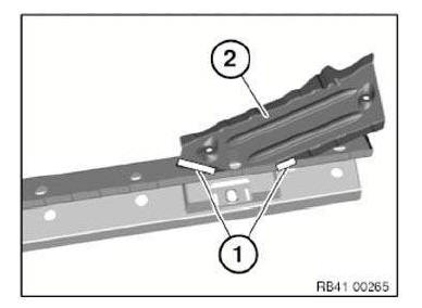
Prepare REINFORCEMENT PLATES at severance cuts.
Installation: Apply sealant to cavity sealing .
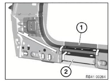
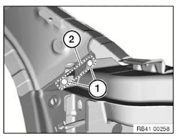
Install and weld new parts and reinforcement plates.
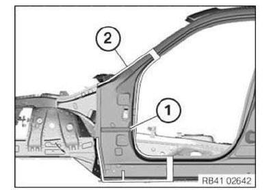
Install new part and reinforcement plate and weld in designated area (1).
Replace B-pillar with reinforcement on left
Procedure OBSERVE repair stage 3! Read contents of BODY, GENERAL.
Use only approved SPOT-WELDING APPARATUS for repairs! Place vehicle on straightening bench.
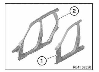
Following new body parts are required :
- (1) Side frame, outer
- (2) Middle side frame
- Shaped part, B-pillar bottom outside
- Shaped part, B-pillar bottom inside
Removal:
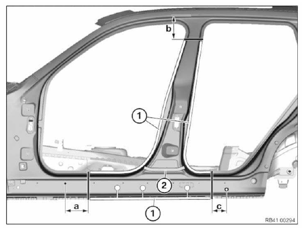
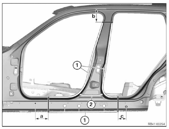
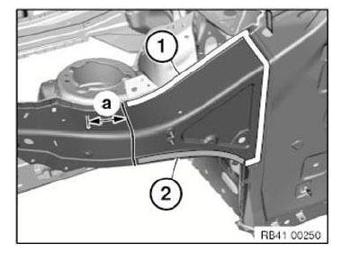
Mark severance cuts in accordance with specified dimensions and cut.
IMPORTANT: Cut outer panel only for following severance cuts.
Dimension a = approx. 180 mm after center point of Ø 8 mm hole.
Dimension b = approx. 175 mm from edge of roof frame.
Dimension c = approx. 105 mm from Ø 20 mm hole.
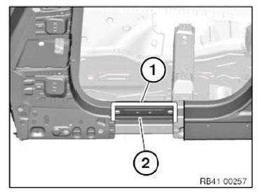
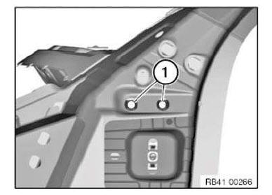
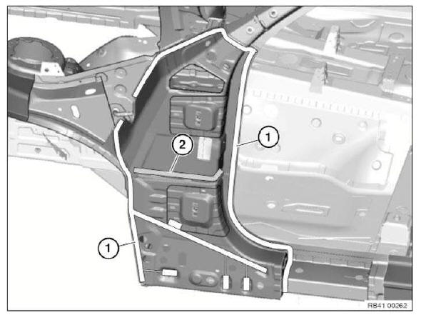
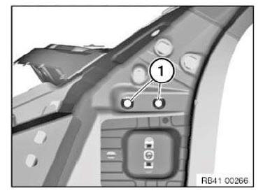
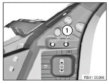
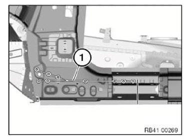
Open welded connections in areas (1).
Release A-pillar from cavity sealing (2) and remove.
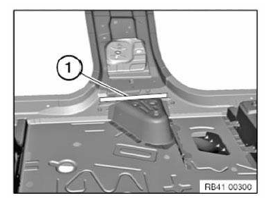
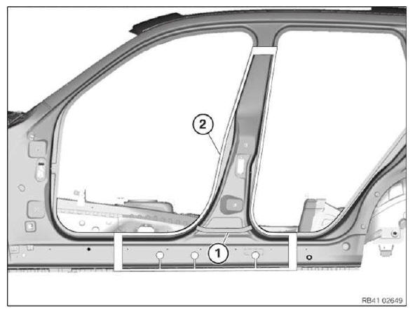
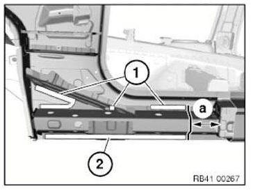
View, B-pillar passenger compartment.
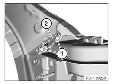
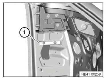
Open welded connections in area (1).
Mark severance cut in accordance with dimension and cut.
IMPORTANT: Cut outer panel only.
Dimension a = approx. 50 mm below previous severance cut.
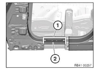
Open welded connections in areas (1).
Release B-pillar reinforcement from cavity sealing (2) and remove.
Preparation of new part: Mark severance cuts on new parts in accordance with severance cuts on vehicle and cut.
Prepare REINFORCEMENT PLATES at severance cuts.
Adjust new parts and reinforcements plates with alignment bracket or universal mount.
Installation:
Apply sealing compound to cavity sealing .
Install new part and reinforcement plate with alignment bracket or universal fixture and weld in designated areas (2).
NOTE: When installing the B-pillar reinforcement new part, the panel thickness of the missing B-pillar outer skin must be taken into consideration depending on the straightening system manufacturer.
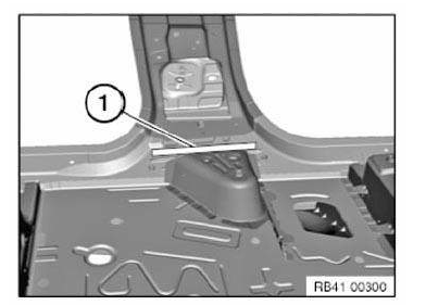
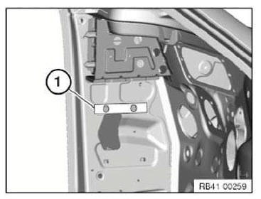
Weld new part in area (1).
Apply sealant to cavity sealing .
Install new part and reinforcement plate and weld in area (2).
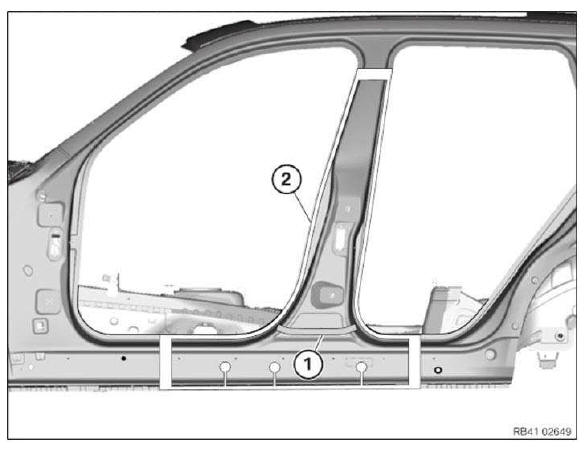
Replace B-pillar, outer left
Procedure OBSERVE repair stage 3!
Read contents of BODY, GENERAL.
Use only an approved SPOT-WELDING APPARATUS for repairs! Following new body parts are required (see OVERVIEW OF CONSUMABLES):
- (1) A-pillar with entrance
- Shaped part, B-pillar bottom outside
Removal:
Mark severance cuts in accordance with specified dimensions and cut.
IMPORTANT: Cut outer panel only for following severance cuts.
Dimension a = approx. 180 mm after center point of Ø 8 mm hole.
Dimension b = approx. 175 mm from edge of roof frame.
Dimension c = approx. 180 mm from center point of Ø 20 mm hole.
Open welded connections in areas (1).
Release A-pillar from cavity sealing (2) and remove.
Preparation of new part: Mark severance cuts on new parts in accordance with severance cuts on vehicle and cut.
Prepare REINFORCEMENT PLATES at severance cuts.
Installation:
Apply sealant to cavity sealing .
Install new parts and reinforcement plates and weld to designated area (2).
Replacing A-pillar with reinforcement on left
Procedure OBSERVE repair stage 3! Read contents of BODY, GENERAL.
Spot-weld bonding is used on this vehicle. Observe specific PROCEDURE.
Use only approved SPOT-WELDING APPARATUS for repairs.
Place vehicle on straightening bench.
Following new body parts are required :
- (1) A-pillar with entrance
- (2) Middle side frame
- (3) Carrier support, outer wheel arch section
- Shaped part A-pillar, top, outer
- Shaped part A-pillar, bottom, outer
Following CONSUMABLES are required:
Removal: Mark severance cut in accordance with dimension and cut.
IMPORTANT: Cut outer panel only.
Dimension a = approx. 120 mm from hole Ø 6 mm.
LOOSEN spot-welded adhesive joints in area (1).
Open welded connections in area (2).
Remove partial section of carrier support.
Mark severance cuts in accordance with specified dimensions and cut.
IMPORTANT: Cut outer panel only for following severance cuts.
Dimension a = approx. 420 mm in front of hole Ø 20 mm.
Dimension b = approx. 450 mm from roof edge.
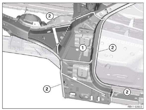
Open welded connections in areas (1).
Open spot-welded adhesive joints in area (2) Release A-pillar outer skin from cavity sealing (3) and remove.
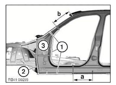
Mark severance cut (1) as pictured and cut.
IMPORTANT: Cut outer panel only.
Open welded connections in area (2).
Open welded connections in area (1).
Remove reinforcement (2).
View of passenger compartment.
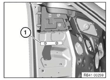
Open welded connections (1).
Open bonded connection in area (2).
Open weld joint in area (1).
Roughly mark severance cut (1) as pictured and cut.
Remove metal section (2).
Open welded connections (1).
NOTE: The welded connections are replaced by bonded rivet connections.
Loosen welded connections using BELT SANDER.

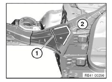
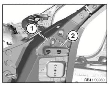
Open welded connections in areas (1).
Release A-pillar from cavity sealing (2) and remove.
Release welded connections in areas (1) and (2) and remove reinforcement (3).
NOTE: Welded connections in the area (1) are replaced by bonded rivet connections.
Preparation of new part:
Mark severance cuts on new parts in accordance with severance cuts on vehicle and cut.
Prepare REINFORCEMENT PLATES at severance cuts.
Detach welded connections.
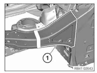
Remove reinforcement (1) and side member attachment (2).
NOTE: The reinforcement (1) is used for installation.
Detach welded connections (1) and take off reinforcement (2).
NOTE: The reinforcement must be installed as a separate component for access reasons.
Mark further severance cuts in accordance with vehicle and cut.
Fit reinforcement (3) in combination with A-pillar reinforcement.
Drill three Ø 6.8 mm bore holes for bonded rivet connections in the designated area (1).
Prepare new part in areas (2) for plug/spot welding.
Adjust and secure A-pillar and reinforcement with alignment bracket or universal fixture.
In areas (1), introduce 2 holes of Ø 6.8 mm for adhesive rivet connection.
For drilling the holes, use TWIST DRILL 6.8 X 156 mm.
NOTE: When adjusting the new part for the A-pillar reinforcement, the panel thickness of the missing A-pillar outer skin must be taken into consideration depending on straightening system manufacturer.
Remove new parts and deburr bore holes.
IMPORTANT: Structure bonding! OBSERVE preparation of bonding surfaces.
Installation: Clean bonding surfaces with cleaning agent R1.
Apply adhesive to bonding surfaces.
Install reinforcement (3).
Rivet new part in designated area (1) using N1 blind rivets and plug-weld in designated areas (2).
IMPORTANT: Risk of damage! Avoid applying too much heat to adjacent adhesive area (1).
Clean bonding surfaces with cleaning agent R1.
Apply adhesive K1 to bonding surfaces.
Apply sealant to cavity sealing .
Install and secure new reinforcement part for A-pillar and reinforcement plates with alignment bracket or universal fixture.
Weld new part in the areas (2).
NOTE: When installing the new part for the A-pillar reinforcement, the panel thickness of the missing A-pillar outer skin must be taken into consideration depending on straightening system manufacturer.
Weld new part in the areas (1).

In designated areas (1), rivet new part with N1 blind rivets.
NOTE: Use RIVET HEAD EXTENSION for this process.
Weld new part in the areas (1).
Install reinforcement (2) and weld in designated area (1).
Install carrier support section and weld in designated area (1).
Replacing A-pillar with reinforcement on the left (with side member attachment)
Procedure OBSERVE repair stage 3! Read contents of BODY, GENERAL.
Spot-weld bonding is used on this vehicle. Observe specific PROCEDURE.
Use only approved SPOT-WELDING APPARATUS for repairs.
Place vehicle on straightening bench.
Following new body parts are required:
- (1) A-pillar with entrance
- (2) Middle side frame
- (3) Carrier support, outer wheel arch section
- Shaped part A-pillar, top, outer
- Shaped part A-pillar, bottom, outer
Following CONSUMABLES are required:
Removal: Mark severance cut in accordance with dimension and cut.
IMPORTANT: Cut outer panel only.
Dimension a = approx. 120 mm from hole Ø 6 mm.
LOOSEN spot-welded adhesive joints in area (1).
Open welded connections in area (2).
Remove partial section of carrier support.
Mark severance cuts in accordance with specified dimensions and cut.
IMPORTANT: Cut outer panel only for following severance cuts.
Dimension a = approx. 420 mm in front of hole Ø 20 mm.
Dimension b = approx. 450 mm from roof edge.
Open welded connections in areas (1).
Open spot-welded adhesive joints in area (2) Release section of A-pillar outer skin from cavity sealing (3) and remove.
Mark severance cut (1) as pictured and cut.
IMPORTANT: Cut outer panel only.
Open welded connections in area (1).
Open welded connections in area (1).
Remove reinforcement (2).
View of A-pillar interior.
Open welded connections (1).
Open bonded connection in area (2).
Open weld joint in area (1).
Roughly mark severance cut (1) as pictured and cut.
Remove metal section (2).
Open welded connections (1).
NOTE: The welded connections (1) are replaced by adhesive rivet connections.
Open welded connections in areas (1).
Release A-pillar from cavity sealing (2) and remove.
Mark severance cut in accordance with dimension and cut.
IMPORTANT: Cut outer panel only.
Dimension a = approx. 120 mm from bulkhead.
Release welded connections in areas (1) and (2) and remove side member attachment with reinforcement.
NOTE: The welded connections in areas (1) are replaced by adhesive rivet connections.
Preparation of new part: Open welded connections (1) and remove reinforcement.
Mark severance cut (2) in accordance with severance cut on vehicle and cut.
NOTE: The reinforcement (1) is used for installation.
Mark further severance cuts on new parts in accordance with severance cuts on vehicle and cut.
Prepare REINFORCEMENT PLATES at severance cuts.
Adjust A-pillar to fit with alignment bracket or universal mount and secure.
In areas (1), introduce 9 holes of Ø 6.8 mm for adhesive rivet connection.
For drilling the holes, use TWIST DRILL 6.8 X 156 mm.
In areas (1), introduce 2 holes of Ø 6.8 mm for adhesive rivet connection.
Remove new parts and deburr bore holes.
IMPORTANT: Structure bonding! OBSERVE preparation of bonding surfaces.
Installation: Clean bonding surfaces with cleaning agent R1.
Apply adhesive to bonding surfaces.
Apply sealant to cavity sealing .
Install new A-pillar and reinforcement plates with alignment bracket or universal mount and fix.
Rivet new part in the areas (1).
Rivet new component in area (1).
If possible move rivets from vehicle interior to the outside.
Weld A-pillar.
Install further new parts and reinforcement plates and weld in place.
REPLACING A-PILLAR WITH REINFORCEMENT, RIGHT
The work is identical to replacing the A-PILLAR WITH LEFT REINFORCEMENT.
REPLACING OUTER RIGHT A-PILLAR
Operation is identical to replacing OUTER LEFT A-PILLAR.
 Wheel wells
...
 Roof outer skin
...
Other materials:
BMW X3 (F25) Service & Repair Manual > Brakes: Front brake
FRONT BRAKE SPECIFICATION
IMPORTANT:
Installation of new brake pads is approved only provided that the brake disc thickness exceeds the
specified dimension for "MIN TH" (see table).
Brake discs must be replaced when they reach the nominal thickness (see table) minus 2.4 mm!(Not
...
