BMW X3 (F25) Service & Repair Manual: Front brakes
OVERVIEW OF FRONT BRAKES
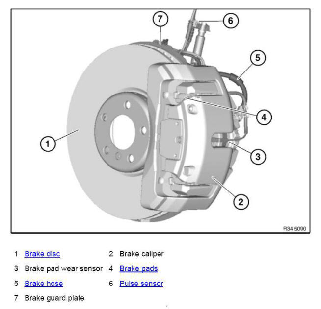
- Precision-turning both front brake discs on both sides
- Removing and installing/renewing brake pads on both front disc brakes
- Removing and installing/replacing both front brake discs
- Removing and installing/replacing left or right front brake caliper
- Removing and installing/replacing vent valve for brake caliper
- Replacing front left or right brake anchor plate/guard plate
Precision-turning both front brake discs on both sides
IMPORTANT: Always precision-turn both sides of both brake discs on one axle.
Maximum machining dimension per friction ring side is 0.8 mm! Observe MINIMUM BRAKE DISC THICKNESS (MIN TH).
Brake discs of M models (Compound brake discs) must not be machined! Only one brake pad set may be used up on brake discs which have been lathe-turned to minimum thickness (MIN TH).
Stationary brake disc lathe:
IMPORTANT: Only BMW-approved brake disc lathes may be used!
In the case of stationary brake disc lathes, the BRAKE DISC must be removed.
Mobile brake disc lathe:
IMPORTANT: Only BMW-approved brake disc lathes may be used!
In the case of mobile brake disc lathes, the brake calipers and brake anchor plates must be removed.
The brake discs remain on the vehicle.
After fine-grinding the brake discs, measure the thickness difference inside the braking surfaces at 8 points with an caliper gauge.
Removing and installing/renewing brake pads on both front disc brakes
Special tools required:
- 34 1 050
- 34 1 280
IMPORTANT:
- Brake pad wear sensor: after removal it must be replaced (brake pad wear sensor loses its retention capability in the break pad).
- Retaining pins and expanding spring: for vehicles older than 48 months it is recommended to replace the retaining spring!
So as not to damage the surface coating, if possible do not mechanically clean the guide surfaces for the brake pads on the brake caliper mounting bracket. Instead, clean with brake cleaner BMW part no. 83 19 2 154 780 and apply a thin coating of brake pad paste BMW part no. 83 19 2 158 851 (3 g) or 83 19 2 158 852 (100 g). Spread brake pad paste onto the marked surfaces using a brush!
Necessary preliminary tasks:
- Remove FRONT WHEELS .
- Remove BRAKE PAD WEAR SENSOR.
NOTE: After completing repair work:
- Fully depress brake pedal several times so that brake pads contact brake discs.
- When installing new brake pads at front and rear axles, brake fluid level must be brought up to "MAX" marking.
- Read and comply with notes on breaking in new brake discs/brake pads.
- When replacing pads, reset CBS display in accordance with factory specification.
Lever out retaining spring (1) in direction of arrow towards rear.
Remove plastic plugs (1).
Unscrew guide bolts (1).
IMPORTANT: Tie brake caliper back and do not allow to hang from brake hose.
Withdraw brake caliper backwards.
Installation note: Only clean guide bolts; do not grease.
Check thread.
Replace all guide screws which are not in perfect condition.
IMPORTANT: Piston-side brake pad is installed directional! Pay attention to direction-of-rotation arrow!
Mark any worn brake pads.
Remove brake pads in direction of arrow.
In the event of one-sided brake pad wear, do not change brake pads round.
Observe MINIMUM THICKNESS OF BRAKE PADS .
Clean brake pads.
Do not apply grease to brake lining backplate.
IMPORTANT: When forcing piston back:
- Pay attention to brake fluid level in expansion tank; brake fluid that spills over will damage paintwork.
Press back brake pads and piston with special tool 34 1 050.
Check minimum brake disc thickness:
- Position special tool 34 1 280 at three measuring points in area (1) and measure.
- Compare measurement result and lowest value with SETPOINT VALUE .
IMPORTANT: New brake pads may only be fitted if the brake disk thickness is greater than the MINIMUM BRAKE DISC THICKNESS (MIN TH).
Check dust boot for damage and renew if necessary.
Clean contact surface (1) of brake piston with brake cleaner and apply a thin coating of brake pad paste.
IMPORTANT: Dust boot must not come into contact with brake pad paste as this may cause the dust boot to swell.
Clean contact surfaces (1) of T-heads/brake caliper housing with brake cleaner and apply a thin coating of brake pad paste.
Clean contact surface (1) of brake caliper with brake cleaner and apply a thin coating of brake pad paste.
So as not to damage the surface coating, if possible do not mechanically clean the guide surfaces (1) for the brake pads on the brake caliper mounting bracket. Clean guide surfaces (1) with brake cleaner and apply a thin coating of brake pad paste.
So as not to damage the surface coating, if possible do not mechanically clean the guide surfaces (1 and 2) for the brake pads on the brake caliper mounting bracket. Clean guide surfaces (1 and 2) with brake cleaner and apply a thin coating of brake pad paste.
Lightly coat the T-head of the inner brake pad with brake pad paste in area (1 and 2).
Lightly coat the T-head of the outer brake pad with brake pad paste in area (1 and 2).
Removing and installing/replacing both front brake discs
Special tools required:
- 34 1 280
Necessary preliminary tasks:
- Remove FRONT WHEELS .
- Remove and clean BRAKE PADS.
NOTE: After completing repair work, read and comply with notes on breaking in new brake discs/brake pads.
Check minimum brake disc thickness:
- Position special tool 34 1 280 at three measuring points in area (1) and measure.
- Compare measuring result and lowest value with SETPOINT VALUE .
NOTE: If the brake discs are replaced, you must also fit new brake pads.
Brake discs may only be replaced in pairs (on each axle)
IMPORTANT: New brake pads may only be fitted if the brake disk thickness is greater than the MINIMUM BRAKE DISC THICKNESS (MIN TH).
Release screws (1). Remove brake-caliper support.
IMPORTANT: To release brake disc: Do not under any circumstances strike friction ring with a hammer or similar! If necessary, carefully tap on base of brake disc chamber with a rubber mallet.
Clean contact surface of brake disc at wheel hub thoroughly and remove traces of corrosion.
Unevenness on contact surface may result in distortion of brake disc!
Release screw (1) and remove brake disc (2).
Installation note: Replace screw.
Removing and installing/replacing left or right front brake caliper
Necessary preliminary tasks:
- REMOVE WHEEL .
- Read and comply with GENERAL INFORMATION.
After completing repair work: BLEED BRAKE SYSTEM.
Press brake pedal down to floor and secure with pedal support.
NOTE: The pedal support may only be released when the brake lines are reconnected.
This prevents brake fluid from emerging from the expansion tank and air from entering the system when the brake lines are opened.
Release retaining screw (1).
If necessary, grip at knurling (2).
IMPORTANT: Never twist brake hose when installing it and avoid all contact with parts attached rigidly to the body.
If necessary, remove brake pad wear sensor.
Lever out retaining spring (1) in direction of arrow towards rear.
Installation note: Place retaining spring (1) first at top and bottom of brake caliper and then allow to engage in recess (2) of brake caliper housing.
Remove plastic plugs (1).
Unscrew guide bolts (1).
Withdraw brake caliper backwards.
Installation note:
Only clean guide bolts; do not grease.
Check threads.
Replace all guide screws which are not in perfect condition.
IMPORTANT: Mark any worn brake pads.
Remove brake pads in direction of arrow.
In the event of one-sided brake pad wear, do not change brake pads round.
If necessary, clean brake caliper and brake pad.
Equipment specification, high-speed brake system.
IMPORTANT: Mark any worn brake pads.
Remove brake pads in direction of arrow.
In the event of one-sided brake pad wear, do not change brake pads round.
If necessary, clean brake caliper and brake pad.
Removing and installing/replacing vent valve for brake caliper
Necessary preliminary work:
- Raise vehicle.
Removal:
Press brake pedal down to floor and secure with pedal support.
NOTE: The pedal support may only be released when the brake lines are reconnected.
This prevents brake fluid from emerging from the expansion tank and air from entering the system when the brake lines are opened.
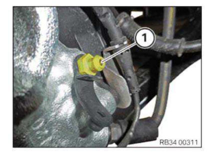
Remove dust cap (1).
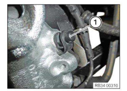
Remove vent valve (1).
IMPORTANT: Collect escaping brake fluid in a suitable collecting vessel.
Installation:
IMPORTANT: The bore hole must be free of contamination!
Install vent valve (1).
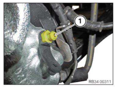
Mount dust cap (1).
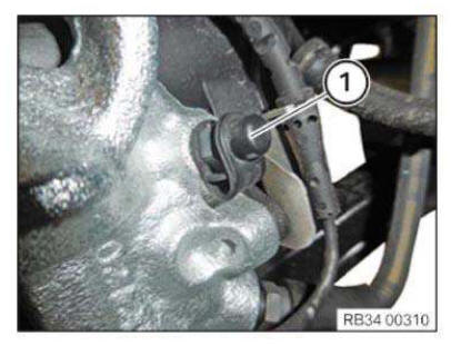
Remove pedal support.
Required follow-up work:
- Bleed brake system.
Replacing front left or right brake anchor plate/guard plate
Necessary preliminary work:
- Remove front BRAKE DISC.
Release screws (1) and remove brake guard plate (2).

 Rear brakes
...
Other materials:
BMW X3 (F25) Service & Repair Manual > Suspension: Spring with suspension
MEASURING VEHICLE RIDE HEIGHT
Determine actual ride height (A) - to do so, attach tape measure to rim flange (2) at bottom middle and measure
to wheel arch lower edge (1).
Removing and installing/replacing coil spring for front left or front right
spring strut
Special tools required:
31 ...
