BMW X3 (F25) Service & Repair Manual: Electronic components
OVERVIEW OF ELECTRONIC COMPONENTS
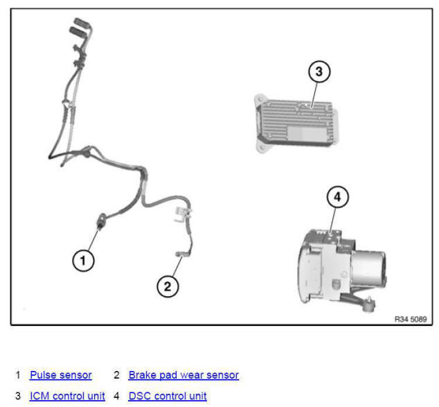
- Removing and installing/renewing icm control unit
- Removing and installing/replacing dsc control unit
- Removing and installing/replacing emf actuator
- Replacing a brake pad sensor (front)
- Replacing a brake pad sensor (rear)
- Replacing a rear pulse generator
- Replacing one front pulse generator
Removing and installing/renewing icm control unit
IMPORTANT: Read and comply with notes on PROTECTION AGAINST ELECTROSTATIC DAMAGE (ESD protection).
WARNING: The sensor system for triggering the airbag is installed in the ICM control unit! The battery must be disconnected before removing the ICM control unit (ICM control unit de-energised)! There is a risk of the airbag being triggered inadvertently if this requirement is disregarded!
Necessary preliminary tasks
- Disconnect negative battery cable.
- Remove CENTER CONSOLE assy.
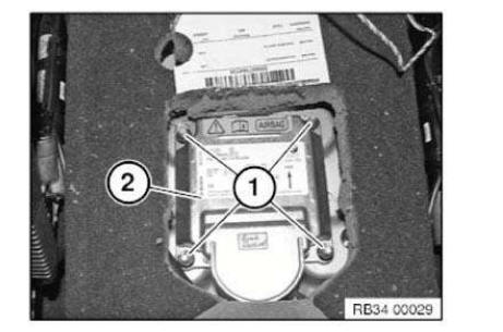
Make service opening (2) in carpet.
Carefully cut carpet along pre-punched line (1).
Fold back service opening (2) in direction of arrow.
WARNING: Make sure that the negative battery lead is disconnected! There is a risk of the airbag being triggered inadvertently!
Undo nuts (1) and raise ICM control unit (2).
Disconnect plug connection and remove ICM control unit (2).
Installation note: Replace self-locking nuts.
IMPORTANT: Do not trap any electrical wires when installing ICM control unit!
After removing and installing ICM control unit:
After completing repairs, use BMW Diagnosis and Information System to
- carry out adjustment/start-up of ICM control unit
After replacement of the ICM control unit:
Vehicles built before 03/2012:
- Adjust vehicle order according to conversion of ICM control unit.
- Program/encode ICM control unit.
- Encode ACSM.
- Carry out ADJUSTMENT/START-UP OF ICM CONTROL UNIT .
- Carry out RIDE HEIGHT ADJUSTMENT .
On vehicles from 03/2012:
After completing repairs, use BMW Diagnosis and Information System to
- Program/encode ICM control unit.
- Carry out ADJUSTMENT/START-UP OF ICM CONTROL UNIT .
- Carry out RIDE HEIGHT ADJUSTMENT .
Removing and installing/replacing dsc control unit
IMPORTANT: Read and comply with notes on PROTECTION AGAINST ELECTROSTATIC DAMAGE (ESD protection).
IMPORTANT: Maintain conditions of absolute cleanliness.
IMPORTANT: Risk of damage to the contacts when removing and installing the hydraulic unit.
Disconnect plug connection (1).
Release screws (2) and carefully detach DSC control unit by pulling forward.
IMPORTANT: Cleaning with compressed air, chemical solvents and sharp-edged objects is not permitted.
Do not touch or clean pressure sensor contacts with your fingers.
If necessary, clean sealing surface (1) with a plastic scraper or a fluff-free cloth.
IMPORTANT: Do not touch, clean or readjust valve coils (1) and pressure sensor contact springs with your fingers.
Check gasket (2) for damage. If damaged, replace DSC control unit (3).
Installation note: Make sure screws are inserted evenly and DSC control unit rests on hydraulic unit.
Replace screws.
Observe tightening sequence (1-4).
Replacement:
- Carry out programming/encoding
- Function check - hydraulic unit
Removing and installing/replacing emf actuator
Necessary preliminary tasks:
- Release parking brake.
- Switch off ignition.
IMPORTANT: Switch off ignition at least 30 s before disconnecting the plug connection!
After installation, observe the following: switch on ignition and, using parking brake operating element, open parking brake once, close once and open again.
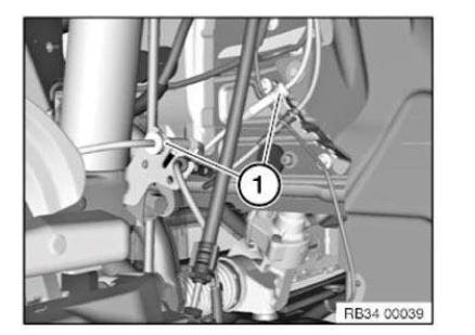
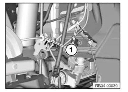
Disconnect plug connection (1).
Disengage cable from cable clip.
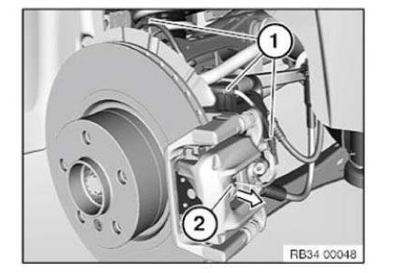
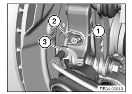
Release screws (1).
Installation note: Replace screws
Take off holder (2).
Detach actuator drive (3) from brake caliper.
Installation note: Check sealing ring (1), replace if necessary.
Apply a light coating of brake fluid to sealing ring (1) before fitting.
Installation note: Carefully fit actuator drive until teeth engage and actuator drive rests flush on brake caliper.
If necessary, turn actuator drive slightly until bore hole and thread are flush.
Replacing a brake pad sensor (front)
IMPORTANT: The brake pad wear sensor must be replaced once it has been removed (brake pad wear sensor loses its retention capability in the brake pad).
If an already ground brake pad wear sensor has to be replaced although the minimum brake pad thickness has not yet been reached, it is necessary to file down the new sliding contact with a file to the same length as the ground sliding contact.
Necessary preliminary work:
- Remove front left WHEEL .
Unclip line from holder (1).
Open housing cover.
Disconnect plug connection (2).
Installation note: Make sure the plug connections snaps in correctly and the line is fitted correctly in the holders.
Unclip line from holders (1).
Installation note: Ensure proper locking of the holders and proper seating of the line in the holders.
Disengage line from brake pad wear sensor from holder (1).
Pull brake pad wear sensor (2) in direction of arrow out of brake pad.
Installation note: Make sure brake pad wear sensor (2) is correctly seated in brake pad and holder (1).
Replacing a brake pad sensor (rear)
IMPORTANT: The brake pad wear sensor must be replaced once it has been removed (brake pad wear sensor loses its retention capability in the brake pad).
If an already ground brake pad wear sensor has to be replaced although the minimum brake pad thickness has not yet been reached, it is necessary to file down the new sliding contact with a file to the same length as the ground sliding contact.
Necessary preliminary work:
- Remove rear right WHEEL .
Open housing cover (1).
Disconnect plug connection for pulse generator.
Unclip line from holders (2).
Installation note: Ensure proper locking of plug connector and proper seating of rubber grommets.
Disengage line from brake pad wear sensor from holders (1).
Pull brake pad wear sensor (2) in direction of arrow out of brake pad.
Installation note: Make sure brake pad wear sensor (2) is correctly seated in brake pad and holder (1).
Replacing a rear pulse generator
IMPORTANT: Read and comply with notes on PROTECTION AGAINST ELECTROSTATIC DAMAGE (ESD protection).
Necessary preliminary work:
- Remove rear WHEEL .
- Read and comply with GENERAL INFORMATION.
Open housing cover (1).
Disconnect plug connection for pulse generator.
Unclip line from holders (2).
Installation note: Ensure proper locking of plug connector and proper seating of rubber grommets.
Release screw (1).
Withdraw wheel speed sensor (2) from bore hole.
Unclip line from holder (3).
Clean bore for pulse generator and lubricate with Staburags NBU 12/K lubricating grease.
IMPORTANT: Prior to installation, check sensor head for damage and replace if necessary.
Replacing one front pulse generator
IMPORTANT: Read and comply with notes on PROTECTION AGAINST ELECTROSTATIC DAMAGE (ESD protection).
Necessary preliminary work:
- Remove front WHEEL .
- Read and comply with GENERAL INFORMATION.
Unclip line from holder (1).
Open housing cover.
Disconnect plug connection (2).
Installation note: Make sure the plug connections snaps in correctly and the line is fitted correctly in the holders.
Unclip line from holders (1).
Installation note: Ensure proper locking of the holders and proper seating of the line in the holders.
Release screw (1) and withdraw pulse generator (2) from bore.
Unclip line from holder (3).
Clean bore for pulse generator and lubricate with Staburags NBU 12/K lubricating grease.
IMPORTANT: Prior to installation, check sensor head for damage and replace if necessary.
START-UP OF ICM CONTROL UNIT
NOTE: Start-up of ICM control unit must be carried out:
- After replacement or removal and installation of ICM control unit
Connect vehicle to BMW diagnosis system.
Select and carry out start-up of ICM control unit under Service functions.

 Brakes
...
Other materials:
BMW X3 (F25) Service & Repair Manual > Body and Frame: Dash cowl
REPLACE THE A-PILLAR ON THE OUTSIDE LEFT IN THE AREA OF THE
WINDSCREEN
Read contents of BODY, GENERAL.
Remove or cover those vehicle components in the repair area which are susceptible to heat or dust.
Use only approved SPOT-WELDING APPARATUS for repairs.
IMPORTANT:
Operations on pyrot ...
