BMW X3 (F25) Service & Repair Manual: Control arms and struts
OVERVIEW OF STEERING LINKS
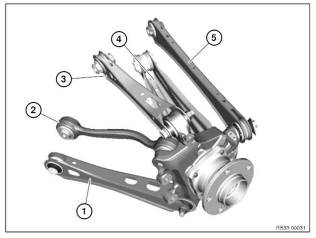
- Removing and installing/replacing a steering stub/wheel carrier
- Removing and installing/replacing left or right camber arm
- Removing and installing/replacing left or right toe arm
- Replacing a ball joint in lower steering stub/wheel carrier
- Replacing a control arm
- Replacing an upper wishbone
- Replacing left or right trailing arm
- Replacing rubber mount for trailing arm in wheel carrier
- Replacing rubber mount for wishbone in wheel carrier
Removing and installing/replacing a steering stub/wheel carrier
Special tools required:
- 33 5 120
- 33 5 125
- 33 5 123
- 33 5 121
- 33 5 124
- 33 5 126
- 33 5 122
Necessary preliminary work:
- Remove REAR WHEEL .
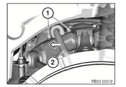
IMPORTANT: Expand anti-twist lock sufficiently to avoid damaging thread when releasing collar nut (1).
Activate parking brake and release collar nut (1).
Installation note: Lightly oil the gearing on the shaft journal.
No oil permitted on thread of shaft journal or collar nut.
Replace collar nut (1) by positive peening at flat areas of output shaft.
IMPORTANT: Special tools 33 5 120 and 33 5 125 must be inserted in all-round slot (1) on output shaft!
Use special tools 33 5 123 , 33 5 121 , 33 5 124 /33 5 126 to push the output shaft out of the rear axle final drive by jerking.
Here, synchronising key of bolt 33 5 122 must rest on rear axle final drive.
Installation note: High installation forces indicate that the output shaft spline teeth are damaged or deformed! Check gearing, replace damaged components.
Check dust plate (1) for damage, renew if necessary.
Circlip (2) must be replaced.
Coat contact surface (3) of output shaft with approved final drive oil.
IMPORTANT:
- The RADIAL SHAFT SEAL FOR THE OUTPUT SHAFT should be replaced every time the output shaft is removed and installed.
- The circlip of the output shaft must be replaced after re-installation.
IMPORTANT: Secure wheel carrier against falling out.
- Loosen the PULSE SENSOR ON THE WHEEL CARRIER .
- Loosen the BRAKE DISC .
- Loosen the ANTI-ROLL BAR LINK ON THE WHEEL CARRIER.
- Loosen SHOCK ABSORBER ON CAMBER ARM.
- Loosen CAMBER ARM ON WHEEL CARRIER.
- Loosen STEERING ARM ON WHEEL CARRIER.
- Loosen UPPER WISHBONE ON WHEEL CARRIER.
- Loosen CONTROL ARM ON WHEEL CARRIER.
- Loosen TRAILING ARM ON WHEEL CARRIER.
Remove wheel carrier including output shaft.
IMPORTANT: Check sensor head and line from pulse sensor prior to installation for external damage, replacing if necessary.
Replacement:
- Press OUTPUT SHAFT out of drive flange.
- Modify BRAKE ANCHOR PLATE/BRAKE GUARD PLATE . Replace if necessary.
- Modify WHEEL BEARING with drive flange. Replace if necessary.
After installation:
- Replacement: Carry out wheel alignment procedure .
Removing and installing/replacing left or right camber arm
IMPORTANT: If the camber arm is bent, the control arm/wheel carrier screw connection must be renewed.
NOTE: If the camber arm is renewed, the wheel alignment .
Necessary preliminary work:
- Remove REAR WHEEL .
Support wheel carrier with workshop jack! Mark position of eccentric adjustment washer to rear axle support to simplify subsequent adjustment of rear axle.
Release nut (1) and remove eccentric bolt.
Installation note: Note insertion direction of eccentric screw.
Renew nut, eccentric bolt.
Tighten down screw connection in NORMAL POSITION .
Release nut (2) and remove screw.
Installation note: Note direction of insertion of screw.
Replace screw and nut.
Release nut (3) and remove screw.
Installation note: Note direction of insertion of bolts.
Replace screw and nut.
After installation:
- Carry out wheel alignment procedure .
Removing and installing/replacing left or right toe arm
IMPORTANT: The toe link must be installed with the opening (U-section) facing downward! If the toe link is bent, the control arm/wheel carrier screw connection must be renewed.
NOTE: If the toe link is detached from the rear axle support, it will be necessary to carry out the wheel alignment procedure .
Necessary preliminary work:
- Remove REAR WHEEL .
Open clips and remove cable for pulse generator.
Installation note: Replace defective clamps.
Release screw (1).
Installation note: Replace screw.
The toe link must be installed with the opening (U-section) facing downward! Tighten down screw connection in NORMAL POSITION .
Mark position of eccentric adjustment washer to rear axle support to simplify subsequent adjustment of rear axle.
Release nut (2) and remove screw.
Installation note: Replace nut.
Tighten down screw connection in NORMAL POSITION .
Installation note: When installing, ensure that the tapered side of the bearing bush is connected first toward the wheel carrier.
After installation:
- Carry out wheel alignment procedure .
REMOVING AND INSTALLING/REPLACING LEFT OR RIGHT UNDERBODY PANELLING
Graphic is only an example. There may be differences in specific details depending on engine version.
Unscrew all bolts.
Remove underbody panelling (1).
Installation note: Make sure underbody panelling (1) is correctly seated.
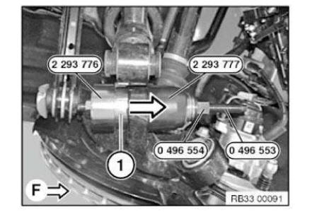
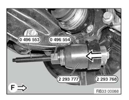
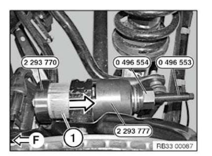
Replacing a ball joint in lower steering stub/wheel carrier
Special tools required:
- 0 496 553
- 2 293 777
- 2 293 775
- 2 293 776
- 0 496 554
Necessary preliminary tasks:
- Remove CAMBER ARM.
- Remove TRAILING ARM.
Pull out ball joint: Pull out ball joint with special tools 0 496 553, 2 293 777 , 2 293 775 and 0 496 553 in direction of travel (F).
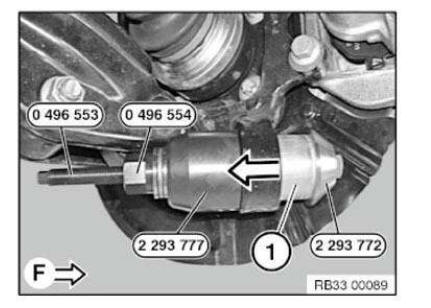
Pull out ball joint: Pull in ball joint (1) with special tools in direction of travel 0 496 553, 2 293 777 , 2 293 776 and 0 496 554 until limit position.
After installation:
- Carry out wheel alignment procedure .
Replacing a control arm
Release screw.
Installation note:
Replace screw.
Tighten down screw connection in NORMAL POSITION .
IMPORTANT: When installing, ensure that the tapered side of the bearing bush is connected first toward the wheel carrier.
Slacken nut (1).
Unscrew bolt towards rear and remove control arm (2).
Installation note:
Bolt head must point to rear.
Replace screw and nut.
Tighten down screw connection in NORMAL POSITION .
Replacing an upper wishbone
IMPORTANT:
- The wishbone must be installed with the opening (U-section) facing downward!
- If the wishbone is bent, the screw connection between the control arm and wheel carrier must be replaced.
Necessary preliminary work:
- Remove REAR WHEEL .
Release left and right screws (1). Slide anti-roll bar (2) forward.
Installation note:
Replace screws.
Release nut (1) and remove screw towards front.
Installation note: Tighten down screw connection in NORMAL POSITION .
Replace screw and nut.
Release nut (1) and remove screw towards front.
Remove wishbone (2).
Installation note: The wishbone must be installed with the opening (U-section) facing downward! Raise wheel carrier using workshop jack.
Bolt heads face in forward direction.
Replace screw and nut.
After installation:
- Carry out wheel alignment procedure .
Replacing left or right trailing arm
IMPORTANT:
- The trailing arm must be installed with the opening (U-section) facing downward!
- If the trailing arm is bent, the control arm/wheel carrier screw connection must be renewed.
Necessary preliminary work:
- Only on left side at ride height sensor: Release JOINTED ROD AT TRAILING ARM .
Unscrew nuts (1).
Pull out bolt towards front.
Installation note: Note direction of insertion of bolts.
Replace screw and nut.
Tighten down screw connection in NORMAL POSITION .
Slacken nut (2).
Move screws toward the rear.
Remove trailing arm (3) downward.
Installation note: The trailing arm must be installed with the opening (U-section) facing downward! Note direction of insertion of screw.
Replace screw and nut.
Tighten down screw connection in NORMAL POSITION .
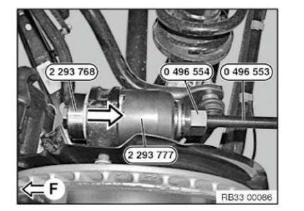
Replacing rubber mount for trailing arm in wheel carrier
Special tools required:
- 0 496 553
- 0 496 554
- 2 293 777
- 2 293 768
- 2 293 772
Necessary preliminary tasks:
- Remove REAR WHEEL .
- Remove TRAILING ARM.
- Remove CAMBER ARM FROM WHEEL CARRIER.
Withdrawing rubber mount: Pull out rubber mount with special tools 0 496 553, 0 496 554, 2 293 777 and 2 293 768 against direction of travel (F).
Installing rubber mount: Pull in rubber mount (1) against direction of travel (F) with special tools 0 496 553, 0 496 554, 2 293 777 and 2 293 772 up to limit position.
Replacing rubber mount for wishbone in wheel carrier
Special tools required:
- 0 496 553
- 0 496 554
- 2 293 768
- 2 293 777
- 2 293 770
Necessary preliminary tasks:
- Release WISHBONE ON WHEEL CARRIER.
Withdrawing rubber mount: Pull out rubber mount with special tools 0 496 553, 0 496 554, 2 293 768 and 2 293 777 out of wheel carrier against direction of travel (F).
Installing rubber mount:
IMPORTANT: Alight slot (1) of rubber mount parallel to wheel carrier.
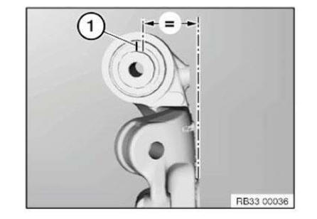
Pull in rubber mount (1) against direction of travel (F) with special tools 0 496 553, 0 496 554, 2 293 770 and 2 293 777 up to limit position.
After installation:
- Perform WHEEL ALIGNMENT .
 Rear sub-frame
...
 Axle mounting
...
Other materials:
BMW X3 (F25) Service & Repair Manual > Brakes: Brake pedal with linkage
REPLACING SPRING FOR BRAKE PEDAL
Necessary preliminary work:
Remove trim panel for pedal mechanism .
Disconnect return spring (1).
REPLACING SPRING FOR CLUTCH PEDAL
Necessary preliminary work:
Remove trim panel for pedal mechanism .
Disconnect return spring (1).
...
