BMW X3 (F25) Service & Repair Manual: Electronic switching or control units
- Coding control module (dme/dde)
- Removing/replacing knock sensor (1st and 2nd cylinder) (N20, N26)
- Removing/replacing knock sensor (3rd and 4th cylinder) (N20, N26)
- Removing/replacing knock sensors (N52T)
- Removing/replacing knock sensors (N55)
- Replacing (dde) control unit (N47 D20 O1)
- Replacing control unit (dme) (N20, N26)
- Replacing control unit (dme) (N52T)
- Replacing control unit (dme) (N55)
- Replacing crankshaft pulse sensor (N20, N26)
- Replacing crankshaft pulse sensor (N52T)
- Replacing crankshaft pulse sensor (N55)
- Replacing pulse sensor on exhaust camshaft (N20)
- Replacing pulse sensor on exhaust camshaft (N52T)
- Replacing pulse sensor on exhaust camshaft (N55)
- Replacing pulse sensor on intake camshaft (N20)
- Replacing pulse sensor on intake camshaft (N55)
- Replacing suction pressure sensor on intake plenum (N20, N26)
- Replacing suction pressure sensor on intake plenum (N55)
- Replacing suction pressure sensor on pressure pipe (N20, N26)
Coding control module (dme/dde)
Switch on ignition.
Connect MoDiC or DIS/GT1 Tester.
Select "Coding" program.
For subsequent procedure, follow instructions in MoDiC or DIS/GT1 Tester.
Carry out adjustment of following control units:
- EWS (electronic immobilizer)
- DME (Digital Motor Electronics) or
- DDE (Digital Diesel Electronics)
Refer to "Diagnosis and Coding" service information bulletins on subject of coding.
PROGRAMMING CONTROL UNIT (DME/DDE)
Switch on ignition.
Connect MoDiC or DIS/GT1 Tester.
Select "Programming".
For subsequent procedure, follow instructions in MoDiC or DIS/GT1 Tester.
Carry out adjustment of following control units:
- EWS (electronic immobilizer)
- DME (Digital Motor Electronics) or
- DDE (Digital Diesel Electronics)
Refer to "Diagnosis and Coding" service information bulletins on subject of programming.
Removing/replacing knock sensor (1st and 2nd cylinder) (N20, N26)
Necessary preliminary tasks:
- Read out the fault memory of the DME control unit.
- Switch off ignition.
- Remove THROTTLE VALVE ASSEMBLY .
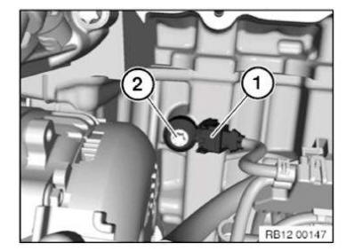
Unlock connector (1) and remove.
Release bolt (2) on knock sensor.
Remove knock sensor for 1st and 2nd cylinder.
Installation note:
Clean contact surface of knock sensors on engine block.
NOTE: Reassemble the vehicle.
Check stored fault message.
Delete fault memory.
Removing/replacing knock sensor (3rd and 4th cylinder) (N20, N26)
Necessary preliminary tasks:
- Read out the fault memory of the DME control unit.
- Switch off ignition.
- Remove STARTER MOTOR.
Unlock connector (1) and remove.
Release bolt (2) on knock sensor.
Remove knock sensor for 3rd and 4th cylinders.
Installation note:
Clean contact surface of knock sensor on engine block.
NOTE: Reassemble the vehicle.
Check stored fault message.
Delete fault memory.
Removing/replacing knock sensors (N52T)
IMPORTANT: Aluminum-magnesium materials.
No steel screws/bolts may be used due to the threat of electrochemical corrosion.
A magnesium crankcase requires aluminum screws/bolts exclusively.
Aluminum screws/bolts must be replaced each time they are released .
Aluminum screws/bolts are permitted with and without color coding (blue).
For reliable identification: Aluminum screws/bolts are not magnetic .
Jointing torque and angle of rotation must be observed without fail (risk of damage) .
Necessary preliminary work:
- Read out the fault memory of the DME control unit.
- Switch off ignition.
- Remove INTAKE PLENUM .
Unlock connector (1) and remove.
Release screws on both knock sensors (1) and remove knock sensors (1).
Installation note:
Replace aluminum screws.
Installation note:
Clean contact surface of knock sensors on engine block.
NOTE: Check stored fault messages.
Clear diagnostic fault entries from fault memory.
Removing/replacing knock sensors (N55)
Necessary preliminary tasks:
- Read out the fault memory of the DME control unit.
- Switch off ignition.
- Remove INTAKE PLENUM .
- Vehicles with the Bosch high pressure pump only :
Remove HIGH PRESSURE PUMP .
Unlock connector (1) and remove.
Feed out connector (1) behind feed line, remove FEED LINE if necessary.
Release screws on both knock sensors (1) and remove knock sensors (1).
Installation note:
Clean contact surface of knock sensors on engine block.
NOTE: Reassemble the vehicle.
Check stored error/fault messages.
Clear diagnostic fault entries from fault memory.
Replacing (dde) control unit (N47 D20 O1)
IMPORTANT: Read and comply with NOTES on protection against electrostatic damage (ESD protection).
Necessary preliminary work:
- Read out the fault memory of the DDE control unit.
- Switch off ignition.
- Disconnect BATTERY EARTH LEAD .
- FOLLOW INSTRUCTIONS FOR REMOVING AND INSTALLING CONTROL UNITS.
Replacement:
- Carry out programming/encoding.
- If no data can be read out from the previous control unit, carry out injection quantity compensation (description at end of instructions).
IMPORTANT: It is absolutely essential to read out the fault memory with the BMW diagnosis system and to create a fault memory printout.
Switch off ignition.
Release screws (1).
Detach coolant hose from cover of electronics box.
Remove electronics box cover (3).
Unlock all connectors (1) from control unit and disconnect.
Detach rubber grommets (2) from electronics box. Place wiring harnesses to the side.
Installation note:
Make sure grommets are correctly fitted (watertightness).
Release retainers (1) on control unit.
Pull out control unit (2) towards top.
Injector adjustment:
If the DDE control unit has been replaced, it will also be necessary to carry out injection quantity compensation! The adjustment value (7-position letter/number code) is engraved on each injector.
Enter the numbers/letters according to the installation position (cylinder) of the injectors.
- Select "DDE".
- Select "Adjustment, injection quantity compensation"
- Select "Test plan"
The adjustment must be entered for each injector.
It is necessary to adjust the injectors to ensure their full operability.
NOTE: Check stored fault messages.
Delete fault memory.
Replacing control unit (dme) (N20, N26)
IMPORTANT: Read and comply with notes on protection against electrostatic damage (ESD protection)
Necessary preliminary tasks:
- Switch off ignition.
- Disconnect BATTERY NEGATIVE LEAD .
- Remove ACOUSTIC COVER
IMPORTANT: Follow INSTRUCTIONS for removing and installing control units
Replacement:
- Carry out programming/encoding
- If no data can be read out from the previous control unit, carry out injection quantity compensation (description at end of instructions).
IMPORTANT: It is absolutely essential to read out the fault memory with the BMW diagnosis system and to create a fault memory printout.
Switch off ignition.
Unlock and pull off all connectors (1) from the DME control unit (2).
Release screws.
Remove DME control unit.
Injection quantity compensation:
If the DME control unit has been replaced, it will also be necessary to carry out adjustment of the injectors! Injection quantity compensation is carried out with the aid of so-called adjustment values.
The adjustment value is printed on each injector in three digits.
The adjustment values must be stored in the new control unit! If injector quantity compensation is not carried out, the engine may run roughly or fail to start.
Read off the adjustment values and enter according to the installation location (cylinder) of the injectors:
- Connect BMW diagnosis system
- Identify vehicle
- Select "Function selection"
- Select "Service functions"
- Select "Engine electronics"
- Select "Adjustment function"
- Select "Adjust injectors"
- Select "Test plan"
- The adjustment value must be entered for each cylinder.
NOTE: Check stored fault message.
Delete fault memory.
Replacing control unit (dme) (N52T)
IMPORTANT: Read and comply with notes on PROTECTION AGAINST ELECTROSTATIC DISCHARGE (ESD PROTECTION)
Necessary preliminary work:
- Switch off ignition.
- Disconnect BATTERY EARTH LEAD .
- Remove ACOUSTIC COVER
IMPORTANT: FOLLOW INSTRUCTIONS FOR REMOVING AND INSTALLING CONTROL UNITS.
Replacement:
- CARRY OUT PROGRAMMING/ENCODING
IMPORTANT: It is absolutely essential to read out the fault memory with the BMW diagnosis system and to create a fault memory printout.
Switch off ignition.
Unlock all plugs from control unit (1) and detach.
Unfasten screws (2).
Remove control unit.
NOTE: Check stored fault messages.
Delete fault memory.
Replacing control unit (dme) (N55)
IMPORTANT: Read and comply with notes on protection against electrostatic discharge (ESD protection).
Necessary preliminary tasks:
- Switch off ignition.
- Disconnect BATTERY NEGATIVE LEAD .
- Remove INTAKE PLENUM .
IMPORTANT: FOLLOW INSTRUCTIONS FOR REMOVING AND INSTALLING CONTROL UNITS.
Replacement:
- Carry out programming/encoding
- If no data can be read out from the previous control unit, carry out injection quantity compensation (description at end of instructions).
IMPORTANT: It is absolutely essential to read out the fault memory with the BMW diagnosis system and to create a fault memory printout.
Switch off ignition.
Release screws (1).
Release screws (1).
Remove control unit from intake plenum.
Installation note:
Renew gasket between intake plenum and control unit.
Injection quantity compensation:
If the DME control unit has been replaced, it will also be necessary to carry out adjustment of the injectors! Injection quantity compensation is carried out with the aid of so-called adjustment values.
The adjustment value is printed on each injector in three digits.
If necessary, remove EMC panel.
The adjustment values must be stored in the new control unit! If injector quantity compensation is not carried out, the engine may run roughly or fail to start.
Read off the adjustment values and enter according to the installation location (cylinder) of the injectors:
- Connect BMW diagnosis system
- Identify vehicle
- Select "Function selection"
- Select "Service functions"
- Select "Engine electronics"
- Select "Adjustment function"
- Select "Adjust injectors"
- Select "Test plan"
- The adjustment value must be entered for each cylinder.
NOTE: Check stored fault message.
Clear diagnostic fault entries from fault memory.
Replacing crankshaft pulse sensor (N20, N26)
IMPORTANT: Read and comply with notes on PROTECTION AGAINST ELECTROSTATIC DISCHARGE (ESD PROTECTION) .
Necessary preliminary tasks:
- Read out the fault memory of the DME control unit.
- Switch off ignition.
- Remove STARTER MOTOR.
Unlock connector (1) and remove.
Release screw (2).
Remove connector housing from crankcase.
Release screw (3).
Pull pulse sensor from crankcase and remove.
Installation note:
During installation of pulse sensor make sure that guide pin (1) of pulse sensor is inserted in guiding groove (2) of crankcase.
NOTE: Assemble engine.
Check stored fault message.
Clear diagnostic fault entries from fault memory.
Replacing crankshaft pulse sensor (N52T)
IMPORTANT: Read and comply with notes on PROTECTION AGAINST ELECTROSTATIC DISCHARGE (ESD PROTECTION) .
IMPORTANT: Aluminum-magnesium materials.
No steel screws/bolts may be used due to the threat of electrochemical corrosion.
A magnesium crankcase requires aluminum screws/bolts exclusively.
Aluminum screws/bolts must be replaced each time they are released .
Aluminum screws/bolts are permitted with and without color coding (blue).
For reliable identification: Aluminum screws/bolts are not magnetic .
Jointing torque and angle of rotation must be observed without fail (risk of damage) .
Necessary preliminary work:
- Read out the fault memory of the DME control unit.
- Switch off ignition.
- Remove INTAKE PLENUM .
NOTE: Installation location of pulse sensor for crankshaft is underneath starter motor.
Detach plug (1) from crankshaft pulse sensor (2).
Release screw.
Installation note:
Replace aluminum screws.
Withdraw pulse sensor (2) from crankcase.
Installation note:
Replace sealing ring.
NOTE: Check stored fault messages.
Delete fault memory.
Replacing crankshaft pulse sensor (N55)
IMPORTANT: Read and comply with notes on PROTECTION AGAINST ELECTROSTATIC DISCHARGE (ESD PROTECTION) .
Necessary preliminary tasks:
- Read out the fault memory of the DME control unit.
- Switch off ignition.
- Remove STARTER MOTOR.
Unlock connector (1) and remove.
Release screw (2).
Remove connector housing from crankcase.
Release screw (3).
Pull pulse sensor from crankcase and remove.
Installation note:
During installation of pulse sensor make sure that guide pin (1) of pulse sensor is inserted in guiding groove (2) of crankcase.
NOTE: Assemble engine.
Check stored fault message.
Delete fault memory.
Replacing pulse sensor on exhaust camshaft (N20)
IMPORTANT: Read and comply with notes on PROTECTION AGAINST ELECTROSTATIC DISCHARGE (ESD PROTECTION) .
Necessary preliminary tasks:
- Read out the fault memory of the DME control unit.
- Switch off ignition.
Unlock connector (1) and remove.
Release screw (2).
Remove pulse sensor (2).
Check gasket, renew damaged gasket.
NOTE: Check stored fault message.
Delete fault memory.
Replacing pulse sensor on exhaust camshaft (N52T)
IMPORTANT: Read and comply with notes on PROTECTION AGAINST ELECTROSTATIC DISCHARGE (ESD PROTECTION) .
Necessary preliminary work:
- Read out the fault memory of the DME control unit.
- Switch off ignition.
- Remove ACOUSTIC COVER
Release screw (1).
Release holder (2) from cylinder head.
Release connector (1) and remove.
Release screw.
Installation note:
Replace screw.
Remove pulse sensor (2).
Installation note:
Replace gasket.
NOTE: Check stored fault messages.
Delete fault memory.
Replacing pulse sensor on exhaust camshaft (N55)
IMPORTANT: Aluminum screws/bolts must be replaced each time they are released .
Aluminum screws/bolts are permitted with and without color coding (blue).
For reliable identification: Jointing torque and angle of rotation must be observed without fail (risk of damage) .
IMPORTANT: Read and comply with notes on PROTECTION AGAINST ELECTROSTATIC DAMAGE (ESD PROTECTION) .
Necessary preliminary work:
- Read out the fault memory of the DME control unit.
- Switch off ignition.
- Remove FAN COWL .
Release connector (1) and remove.
Release screw.
Remove pulse sensor (2).
NOTE: Check stored fault message.
Delete fault memory.
Replacing pulse sensor on intake camshaft (N20)
IMPORTANT: Read and comply with notes on PROTECTION AGAINST ELECTROSTATIC DISCHARGE (ESD PROTECTION) .
Necessary preliminary tasks:
- Read out the fault memory of the DME control unit.
- Switch off ignition.
Unlock connector (1) and remove.
Release screw.
Remove pulse sensor (2).
Check gasket, renew damaged gasket.
NOTE: Check stored fault message.
Delete fault memory.
IMPORTANT: Read and comply with notes on PROTECTION AGAINST ELECTROSTATIC DISCHARGE (ESD PROTECTION) .
Necessary preliminary work:
- Read out the fault memory of the DME control unit.
- Switch off ignition.
- Remove ACOUSTIC COVER
Release connector (1) and remove.
Release screw.
Installation note:
Replace screw.
Remove pulse sensor (2).
Installation note:
Replace sealing ring.
NOTE: Check stored fault messages.
Delete fault memory.
Replacing pulse sensor on intake camshaft (N55)
IMPORTANT: Aluminum screws/bolts must be replaced each time they are released .
Aluminum screws/bolts are permitted with and without color coding (blue).
For reliable identification: Jointing torque and angle of rotation must be observed without fail (risk of damage) .
IMPORTANT: Read and comply with notes on PROTECTION AGAINST ELECTROSTATIC DAMAGE (ESD PROTECTION) .
Necessary preliminary work:
- Read out the fault memory of the DME control unit.
- Switch off ignition.
- Remove FAN COWL .
Release connector (1) and remove.
Release screw.
Remove pulse sensor (2).
NOTE: Check stored fault message.
Delete fault memory.
Replacing suction pressure sensor on intake plenum (N20, N26)
Necessary preliminary tasks:
- Read out the fault memory of the DME control unit.
- Switch off ignition.
- Partially undo the acoustic cover.
Unlock connector (1) and remove.
Unfasten screws (2).
Pull out the vacuum pressure sensor (3) from the intake plenum.
Installation note:
Check sealing ring for damage. Replace damaged sealing ring.
When installing, coat sealing ring with suitable lubricant.
NOTE: Reassemble the vehicle.
Check stored fault message.
Delete fault memory.
Replacing suction pressure sensor on intake plenum (N55)
Necessary preliminary work:
- Read out the fault memory of the DME control unit.
- Switch off ignition.
- Remove INTAKE FILTER HOUSING .
Release connector (1) and remove.
Release screws and pull suction pressure sensor (2) out of intake plenum.
Installation note:
Check sealing ring for damage. Replace damaged sealing ring.
When installing, coat sealing ring with suitable lubricant.
NOTE: Reassemble the vehicle.
Check stored fault message.
Delete fault memory.
Replacing suction pressure sensor on pressure pipe (N20, N26)
Necessary preliminary tasks:
- Read out the fault memory of the DME control unit.
- Switch off ignition.
Unlock connector (1) and remove.
Unfasten screws (2).
Pull suction pressure sensor (3) out of pressure pipe.
Installation note:
Check sealing ring for damage. Replace damaged sealing ring.
When installing, coat sealing ring with suitable lubricant.
NOTE: Reassemble the vehicle.
Check stored fault message.
Delete fault memory.
 Ignition coil
...
 Preheating relay
REPLACING PREHEATING CONTROL UNIT (N47D20 O1)
Necessary preliminary tasks:
Switch off ignition.
Remove INTAKE SILENCER HOUSING .
Release pos ...
Other materials:
BMW X3 (F25) Service & Repair Manual > Driveline+Axles: General information on final drive oil
1.0 GENERAL INFORMATION ON FINAL DRIVE OIL
Final Drive oil or hypoid gear lubricant must conform with the following requirements because of the high
loads which occur on the profiles of the hypoid gear teeth:
Load carrying capacity.
Sufficient protection against seizure.
Good wear protec ...
