BMW X3 (F25) Service & Repair Manual: Brake testing and bleeding
- Bleeding brake system with dsc
- Checking brakes on test stand
- Checking thickness of brake pad
- General notes
- Guideline for applying brake pad paste on brake pads and brake anchor plate
- Minimum brake disc thickness
- Parking brake (emf) - additional brake bleeding procedure
- Parking brake function check
- Removing and installing/replacing vent valve for brake caliper
- Replacing fluid in brake system
- Safety information for working on vehicles with automatic engine start-stop function (msa)
Bleeding brake system with dsc
Necessary preliminary tasks:
- Remove left sensor opening.
- Read and comply with GENERAL INFORMATION.
IMPORTANT: Under certain circumstances it is not possible after the brake system is opened to bleed the brake system fully at the rear EMF brake calipers. If there is still residual air in the rear brake calipers after normal bleeding, it will be necessary to work through an ADDITIONAL BLEEDING PROCEDURE!
When replacing or repairing, observe the filling and bleeding instructions for the following parts:
- Tandem brake master cylinder.
- Hydraulic unit.
- Components and lines which are fitted between these assemblies.
Connect bleeder unit with max. 2 bar filling pressure.
A second person is needed for this repair work.
Use only BMW-approved brake fluids.
Connect diagnosis and information system.
Select path: Service functions - Chassis/Suspension - Traction control systems - Bleeding procedure.
IMPORTANT: Check relevant equipment manufacturer's operating instructions for each device.
Charging pressure should not exceed 2 bar.
Connect bleeder unit to expansion tank and switch on.
Completely bleed the brake system.
Connect bleeder hose with collecting tray to bleeder valve on rear right brake caliper.
Open bleeder valve and purge until clear, bubble-free brake fluid emerges.
Close vent valve.
Follow same procedure on rear left, front right and front left wheel brake.
IMPORTANT: In vehicles with 6-piston fixed caliper brakes two vent valves per brake caliper are installed on the front axle! In each case start by bleeding at the outer vent valve and then bleed at the inner vent valve.
Bleed the rear axle brake circuit. Connect bleeder hose with collecting tray to bleeder valve on rear right brake caliper.
Open vent valve.
Run brake bleeding procedure using the diagnosis and information system with the vent valve open.
After completing routine, press brake pedal 5 times to floor; clear and bubble-free brake fluid must flow out.
Close vent valve.
Repeat procedure at rear left.
Bleed front-axle brake circuit.
Connect vent hose with collecting vessel to vent valve on front right brake caliper.
Open vent valve.
IMPORTANT: In vehicles with 6-piston fixed caliper brakes two vent valves per brake caliper are installed on the front axle! In each case start by bleeding at the outer vent valve and then bleed at the inner vent valve.
Run brake bleeding procedure using the diagnosis and information system with the vent valve open.
After completing routine, press brake pedal 5 times to floor, clear and bubble-free brake fluid must flow out.
Close vent valve.
Repeat procedure at front left.
Switch off bleeder unit and remove from expansion tank.
Check brake fluid level. If necessary, top up/draw off to "MAX" level.
Close expansion tank.
NOTE: Pay attention to gasket (1) in sealing cap.
Checking brakes on test stand
Necessary preliminary work:
- Check tires for damage.
- Check tire treads.
- Checking tire inflation pressure.
IMPORTANT: Make sure the Hill Descent Control (HDC) is not active before driving on to the brake test rig! The Hill Descent Control (HDC) indicator light must not be on!
The brakes must be at normal operating temperature. To do so, gently warm up the brake discs and brake drums while dry by braking the vehicle several times.
IMPORTANT: Only brake test stands with test speeds of 2.5-6 km/h may be used.
Max. bedding-in time 2 minutes.
You must follow without fail the guidelines contained in the operating instructions of the relevant test stand manufacturer.
Failure to do so may result in damage to the vehicle and the system and also personal injury.
Front axle on brake test rig:
IMPORTANT: No gear or drive range must be engaged! Selector lever position "Neutral" on automatic transmission vehicles.
Do not press accelerator! Disregard of these instructions will result in the transfer box engaging, forcing the vehicle off the brake test rig!
Drive vehicle on to brake test rig and carry out brake test.
Rear axle on brake test rig:
IMPORTANT: No gear or drive range must be engaged! Selector lever position "Neutral" on automatic transmission vehicles.
Do not press accelerator! Disregard of these instructions will result in the transfer box engaging, forcing the vehicle off the brake test rig!
Drive vehicle onto brake test stand
The vehicle utilises a plausibility check (wheel speed comparison) to detect the brake test rig within a few seconds and switches to brake test rig mode.
The parking brake indicator light flashes slowly when brake test stand mode is activated and parking brake actuators are released.
Following indicator lights are permanently on:
- Parking brake
- Brake system
- Dynamic stability control (DSC)
- Antilock Brake System ABS
Actuate parking brake switch = application of brake pads.
The parking brake indicator light flashes quickly when brake test stand mode is activated and parking brake actuators are partially locked.
Actuate parking brake switch = test force 1
Actuate parking brake switch again = test force 2
Actuate parking brake switch again = test force 3
The parking brake is released again when the button is actuated in the Release direction.
The parking brake indicator light is permanently activated when brake test stand mode is not detected and parking brake actuators are fully locked.
Brake test stand mode is automatically terminated when the vehicle is driven off the brake test stand.
All indicator lights go out automatically!
Checking thickness of brake pad
Special tools required:
- 34 1 260
NOTE: The thickness of the outer brake pads can be determined without removing the wheels.
If necessary, move vehicle until opening for brake pad wear indicator (brake pad) can be seen through rim styling.
Insert special tool 34 1 260 wheel rim into opening for brake pad wear indicator.
Press special tool onto brake pad. Slide ring (1) in direction of arrow up to stop and read off measured value.
NOTE:
A. Brake disc
B. Brake pad with backplate
General notes
The brake system is one of the most important safety systems in the vehicle. Therefore, it is important to exercise special care when performing repair work on the brake system and to adhere to the following instructions.
- Ensure cleanliness and use only fluff-free cleaning cloths.
- Wash away or vacuum up brake dust, do not clear it away using compressed air. This dust is a health hazard.
- Oil or grease must never enter the brake system. This would result in failure of the entire brake system.
- When cleaning brake components with brake cleaner, never let brake cleaner enter the brake system.
- Even a minute amount of brake cleaner residue must be avoided.
- Replace brake fluid at least every two years.
- Important: Never reuse drained off brake fluid.
- Use only BMW-approved brake fluid.
- Dispose of brake fluid in approved appliances only.
- Do not allow brake fluid to drain into drain pipes, into the outside environment or into unsuitable facilities. This would create the risk of groundwater contamination since brake fluid is classed as a fluid that is hazardous to water.
- Do not allow brake fluid to come into contact with paintwork as this will destroy the paint.
- Brake fluid must not be allowed to remain on bare skin too long in order to avoid skin problems. Wash skin coated with brake fluid with water and soap.
- If brake fluid makes contact with eyes, immediately flush with large quantity of clean water and visit eye doctor.
- Brake pads:
Brake pads must be replaced when the remaining brake pad thickness is reached.
Brake pads must always be replaced on both sides of any axle.
The friction surfaces of the brake pads must not come into contact with oil or grease. The brake pads must be replaced if they are dirt contamination by such substances.
In the case of rotation-dependent brake pads, make sure the arrow marking points in the direction of rotation of the brake disc for when the vehicle is moving forward. Brake pads with left/right markings must be fitted on the relevant side of the vehicle.
One-sided angled areas on the brake pads must be located on the disc contact side of the brake caliper for when the vehicle is moving forward.
- Brake discs:
Brake discs must not be scored or cracked. Furthermore, minimum brake disc thickness, disc runout,
parallelism and surface roughness of the friction surfaces must not exceed or drop below the permitted
values.
Always strip preservative off new parts before installation. With the rear brake discs, also strip preservative off brake drum on parking brake.
- Always strip preservative off new parts before installation.
- Brake calipers:
Only approved glycol-based assembly pastes may be used for repairs on brake calipers.
All moving components on the brake caliper must move freely: note grease specifications.
Use only BMW-approved lubricants to grease the brake caliper guides.
- Brake lines and brake hoses must be correctly routed and must not abut with body or components in a way which would cause chafing.
- To prevent damage, release and tighten brake line couplings with a special brake line wrench only.
- The system must be bled each time any brake lines have been detached.
- All connection points must be checked for leaks.
- Only tighten down brake hoses on the front axle when wheels are in straight-ahead driving position.
- Close open connections on brake lines and individual components to prevent dirt from entering the brake system.
- Observe TIGHTENING TORQUE when tightening down brake line couplings.
The traction control system is basically maintenance-free. However, be sure to adhere to the following:
- When carrying out welding work with electric welder, be sure to disconnect the connector from the electronic control unit (ignition turned off).
- During painting work, the control unit may be subjected for brief periods to max. 95 ºC and for long periods (approx. 2 hours) to max. 85 ºC.
- Battery clamps must be completely tight on battery terminals.
- The brake lines on the hydraulic unit must not be mixed up; if necessary, mark them prior to disassembly.
- On completion of repair work, carry out mix-up test with the DIS diagnosis system.
Guideline for applying brake pad paste on brake pads and brake anchor plate
IMPORTANT: So as not to damage the surface coating, if possible do not mechanically clean the guide surfaces for the brake pads on the brake caliper mounting bracket. Instead, clean with brake cleaner BMW part no. 83 19 2 154 780 and apply a thin coating of brake pad paste BMW part no. 83 19 2 158 851 (3 g) or 83 19 2 158 852 (100 g).
Spread brake pad paste onto the marked surfaces using a brush!
- Brake pad paste 100 gr. BMW part no. 83 19 2 158 852
- Brake pad paste 3 gr. BMW part no. 83 19 2 158 851
- Brush for spreading brake pad paste over the marked areas.
Brake IPS (CBI) 1-piston floating caliper brake (model ranges: 1-Series, 3-Series, 4-Series, X3)
Clean contact surface (1) of brake piston with brake cleaner and apply a thin coating of brake pad paste.
Clean contact surfaces (1) of T-heads/brake caliper housing with brake cleaner and apply a thin coating of brake pad paste.
Clean contact surface (1) of brake caliper with brake cleaner and apply a thin coating of brake pad paste.
So as not to damage the surface coating, if possible do not mechanically clean the guide surfaces (1) for the brake pads on the brake caliper mounting bracket. Clean guide surfaces (1 and 2) with brake cleaner and apply a thin coating of brake pad paste.
So as not to damage the surface coating, if possible do not mechanically clean the guide surfaces (1 and 2) for the brake pads on the brake caliper mounting bracket. Clean guide surfaces (1 and 2) with brake cleaner and apply a thin coating of brake pad paste.
Apply a thin coating of brake pad paste to T-head of inner brake pad in area (1) and (2).
Apply a thin coating of brake pad paste to T-head of outer brake pad in area (1) and (2).
Brake FN (Continental Teves) 1-piston floating caliper brake (model ranges: 5-Series, 6-Series, 7-Series, 8-Series, X1, X3, X5, Z4, RR)
Clean contact surface (1) of brake piston with brake cleaner and apply a thin coating of brake pad paste.
Clean contact surfaces (1) of T-heads/brake caliper housing with brake cleaner and apply a thin coating of brake pad paste.
Clean contact surface (1) of brake caliper with brake cleaner and apply a thin coating of brake pad paste.
So as not to damage the surface coating, if possible do not mechanically clean the guide surfaces (1) for the brake pads on the brake caliper mounting bracket. Clean guide surfaces (1) with brake cleaner and apply a thin coating of brake pad paste.
So as not to damage the surface coating, if possible do not mechanically clean the guide surfaces (1 and 2) for the brake pads on the brake caliper mounting bracket. Clean guide surfaces (1 and 2) with brake cleaner and apply a thin coating of brake pad paste.
Lightly coat the T-head of the inner brake pad with brake pad paste in area (1 and 2).
Lightly coat the T-head of the outer brake pad with brake pad paste in area (1 and 2).
Brake FN (Continental Teves) 2-piston floating caliper brake (model ranges: 5-Series, 6-Series, 7-Series, 8-Series, X5, RR)
Clean contact surface (2) of brake piston with brake cleaner and apply a thin coating of brake pad paste.
Clean contact surfaces (1) of T-heads/brake caliper housing with brake cleaner and apply a thin coating of brake pad paste.
Clean contact surface (1) and brake caliper with brake cleaner and apply a thin coating of brake pad paste.
So as not to damage the surface coating, if possible do not mechanically clean the guide surfaces (1 and 2) for the brake pads on the brake caliper mounting bracket. Clean guide surfaces (1 and 2) with brake cleaner and apply a thin coating of brake pad paste.
So as not to damage the surface coating, if possible do not mechanically clean the guide surfaces (1 and 2) for the brake pads on the brake caliper mounting bracket.
Clean guide surfaces (1 and 2) with brake cleaner and apply a thin coating of brake pad paste.
Lightly coat the T-head of the inner brake pad with brake pad paste in area (1 and 2).
Lightly coat the T-head of the outer brake pad with brake pad paste in area (1 and 2).
Brake Collette (TRW) 1-piston brake caliper (model ranges: MINI, 1-Series, 5-Series, 6-Series, Z4)
Clean contact surface (1) of brake piston with brake cleaner and apply a thin coating of brake pad paste.
Clean contact surface (1) of brake caliper with brake cleaner and apply a thin coating of brake pad paste.
So as not to damage the surface coating, if possible do not mechanically clean the guide surface (1) for the brake pads on the brake caliper mounting bracket. Clean guide surface (1) with brake cleaner and apply a thin coating of brake pad paste.
Apply a thin coating of brake pad paste to both sides of T-head of brake pad in area (1).
Brake P 4.40 (Brembo) 4-piston fixed caliper brake (model ranges: MINI, 1-Series, 3-Series, 4-Series, 5- Series, 6-Series, 7-Series, 8-Series, X5, RR)
Clean contact surface (1) of brake piston with brake cleaner and apply a thin coating of brake pad paste.
So as not to damage the surface coating, if possible do not mechanically clean the guide surfaces (2) for the brake pads on the brake caliper mounting bracket. Clean guide surface (2) with brake cleaner and apply a thin coating of brake pad paste.
Clean both inner and outer guide surfaces (2) and apply a thin coating of brake pad paste.
Lightly coat both sides of the contact surface in area (1 and 2) with brake pad paste.
Lightly coat the brake pad contact surface on both sides in area (1) with brake pad paste.
Brake P 4.40 (Brembo) 2-piston fixed caliper brake (model ranges: 1-Series, 3-Series)
Clean contact surface (1) of brake piston with brake cleaner and apply a thin coating of brake pad paste.
So as not to damage the surface coating, if possible do not mechanically clean the guide surfaces (2) for the brake pads on the brake caliper mounting bracket. Clean guide surface (2) with brake cleaner and apply a thin coating of brake pad paste.
Clean both inner and outer guide surfaces (2) and apply a thin coating of brake pad paste.
Lightly coat both sides of the contact surface in area (1 and 2) with brake pad paste.
Lightly coat the brake pad contact surface on both sides in area (1) with brake pad paste.
Minimum brake disc thickness
NOTE: New brake pads may only be fitted if the brake disc thickness is greater than the minimum brake disc thickness (MIN TH).
Test specification <!-- [sect] --> 29 Limit value for brake disc thickness:
- BMW, MINI and Rolls-Royce vehicles: nominal dimension minus 2.4 mm.
- Vehicles of BMW Motorsport (perforated brake disc): nominal dimension minus 1.6 mm.
This limit dimensions is also applicable to perforated brake discs which are fitted on BMW AG vehicles as optional accessories!
- Minimum thickness of brake pads: 3 mm.
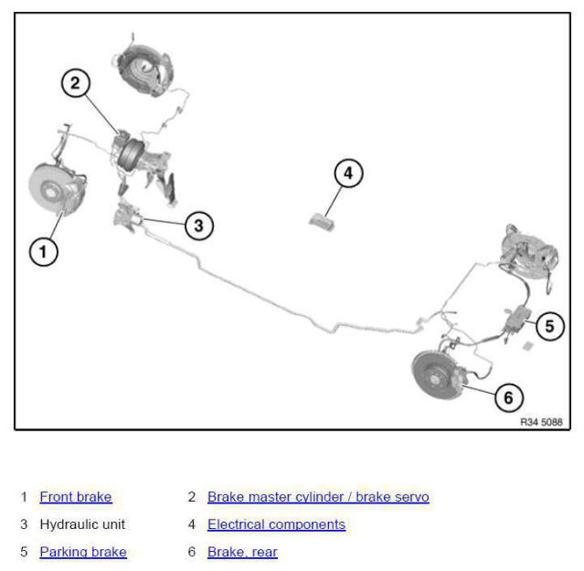
OVERVIEW OF BRAKES
Parking brake (emf) - additional brake bleeding procedure
NOTE: This bleeding procedure serves to eliminate residual air in the brake system.
Under certain circumstances it may not be possible to remove the entire residual air from the parking brake (EMF) brake calipers by means of the normal bleeding procedure.
In these cases, the following procedure applies.
Connect brake fluid changer to expansion tank and switch on.
NOTE: Check relevant equipment manufacturer's Operating Instructions for each device.
Charging pressure should not exceed 2 bar.
Close vent valve.
Flush brake caliper in installation position.
Close vent valve.
Unscrew guide bolts (1).
If necessary, grip at hexagon head (2).
Remove brake caliper (3).
Installation note: Replace guide bolts.
Disconnect plug connection on EMF actuator and detach cable from cable clip.
Turn brake caliper so that EMF actuator points downwards.
Open vent valve and flush brake caliper.
Close vent valve.
Turn brake caliper so that EMF actuator points upwards.
Open vent valve and flush brake caliper.
Close vent valve.
Reinstall brake caliper in installation position and flush again.
Switch off brake fluid changer and remove from expansion tank.
Check brake fluid level. If necessary, top up/draw off to max. level.
Close expansion tank.
NOTE: Pay attention to rubber seal (1) in sealing cap.
Parking brake function check
IMPORTANT: Follow instructions for Brake testing on test stand.
Rear axle on brake test rig:
IMPORTANT: No gear or drive range must be engaged! Selector lever position "Neutral" on automatic transmission vehicles.
Do not press accelerator! Disregard of these instructions will result in the transfer box engaging, forcing the vehicle off the brake test rig!
Drive vehicle onto brake test stand The vehicle utilises a plausibility check (wheel speed comparison) to detect the brake test rig within a few seconds and switches to brake test rig mode.
The parking brake indicator light flashes slowly when brake test stand mode is activated and parking brake actuators are released.
Following indicator lights are permanently on:
- Parking brake
- Brake system
- Dynamic stability control (DSC)
- Antilock Brake System ABS
Actuate parking brake switch = application of brake pads.
The parking brake indicator light flashes quickly when brake test stand mode is activated and parking brake actuators are partially locked.
Actuate parking brake switch = test force 1
Actuate parking brake switch again = test force 2
Actuate parking brake switch again = test force 3
The parking brake is released again when the button is actuated in the Release direction.
The parking brake indicator light is permanently activated when brake test stand mode is not detected and parking brake actuators are fully locked.
Brake test stand mode is automatically terminated when the vehicle is driven off the brake test stand.
All indicator lights go out automatically! Checking brake force differential at wheel:
Apply parking brake until a wheel circumferential force (measured on brake test stand) of min. 1000 N is reached.
Max. permitted brake force differential right/left ≤35 % (referred to greater brake value).
Removing and installing/replacing vent valve for brake caliper
Necessary preliminary work:
- Raise vehicle.
Removal:
Press brake pedal down to floor and secure with pedal support.
NOTE: The pedal support may only be released when the brake lines are reconnected.
This prevents brake fluid from emerging from the expansion tank and air from entering the system when the brake lines are opened.
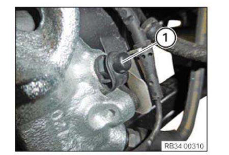
Remove dust cap (1).
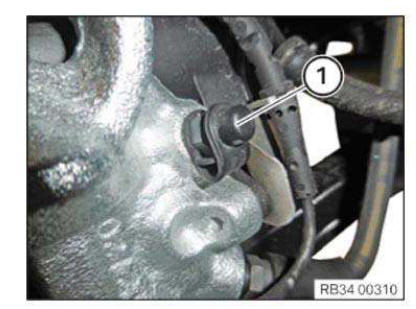
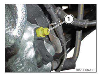
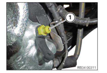
Remove vent valve (1).
IMPORTANT: Collect escaping brake fluid in a suitable collecting vessel.
Installation:
IMPORTANT: The bore hole must be free of contamination!
Install vent valve (1).
Mount dust cap (1).
Remove pedal support.
Required follow-up work:
- Bleed brake system.
Replacing fluid in brake system
Necessary preliminary tasks:
- Remove left sensor opening
IMPORTANT: When carrying out repairs to the brake system, follow the procedure set out in BLEEDING BRAKE SYSTEM WITH DSC.
Under certain circumstances it is not possible after the brake system is opened to bleed the brake system fully at the rear EMF brake calipers. If there is still residual air in the rear brake calipers after normal bleeding, it will be necessary to work through an ADDITIONAL BRAKE BLEEDING PROCEDURE! Use only BMW-approved brake fluids.
Connect bleeder unit to expansion tank and switch on.
NOTE: Follow the applicable equipment manufacturer's Owner's Handbook.
Charging pressure should not exceed 2 bar.
Completely bleed the brake system. Connect bleeder hose with collecting tray to bleeder valve on rear right brake caliper.
Open bleeder valve and purge until clear, bubble-free brake fluid emerges.
Close vent valve.
Follow same procedure on rear left, front right and front left wheel brake.
IMPORTANT: In vehicles with 6-piston fixed caliper brakes two vent valves per brake caliper are installed on the front axle! In each case start by bleeding at the outer vent valve and then bleed at the inner vent valve.
Switch off bleeder unit and remove from expansion tank.
Check brake fluid level. If necessary, top up/draw off to "Maximum" level.
Close expansion tank.
NOTE: Pay attention to gasket (1) in sealing cap.
Safety information for working on vehicles with automatic engine start-stop function (msa)
WARNING: If the engine hood/bonnet contact is pulled upwards (workshop mode), the information "switch closed" is output. The automatic engine start-stop function is active.
An automatic engine start is possible.
Observe safety precautions when working on MSA vehicles.
Before carrying out practical work on the engine, always ensure that the MSA functionality is deactivated so as to prevent automatic engine starting while work is being carried out in the engine compartment.
MSA function is deactivated by:
- Deactivate MSA by means of button (1) in passenger compartment
- Open seat belt buckle and driver's door
- Open engine bonnet/hood and ensure that engine hood/bonnet contact is not in workshop mode
- Workshop mode
A = 10 mm- Basic setting (engine hood/bonnet open)
B = 7 mm
To make sure that the engine hood/bonnet contact is at the basic setting, if necessary press the hood/bonnet contact up to the limit position before starting work and slowly release.
 Handling brake fluids
Brake fluids could be mixed up accidentally with mineral oil products so it is important to leave them in their
original containers and not pour th ...
 Front brakes
OVERVIEW OF FRONT BRAKES
...
Other materials:
BMW X3 (F25) Owners Manual > Notes: Event Data Recorder EDR
This vehicle is equipped with an event data recorder
EDR. The main purpose of an EDR is to
record, in certain crash or near crash-like situations,
such as an air bag deployment or hitting
a road obstacle, data that will assist in understanding
how a vehicle's systems performed.
The EDR is de ...
