BMW X3 (F25) Service & Repair Manual: Rear axle repair instructions
- Danger of poisoning if oil is ingested/absorbed through the skin
- Information on replacing shock absorbers
- Lifting the vehicle using a vehicle hoist
- Raising vehicle with trolley jack
- Risk of injury if oil comes into contact with eyes and skin
- Safety instructions for handling oil
- Removing and installing/replacing rear differential
- Replacing shaft seal(s) for output shaft(s) in rear axle final drive
Danger of poisoning if oil is ingested/absorbed through the skin
Danger of poisoning!
Ingesting oil or absorbing through the skin may cause poisoning!
Possible symptoms are:
- Headaches
- Dizziness
- Stomach aches
- Vomiting
- Diarrhoea
- Cramps/fits
- Unconsciousness
Protective measures/rules of conduct:
- Pour oil only into appropriately marked containers
- Do not pour oil into drinking vessels (drinks bottles, glasses, cups or mugs)
- Observe country-specific safety regulations
First aid measures:
- Do not induce vomiting.
If the person affected is still conscious, he/she must rinse out their mouth with water, drink plenty of water and consult a doctor immediately.
If the person affected is unconscious, do not administer anything by mouth, place the person in the recovery position and seek immediate medical attention.
Information on replacing shock absorbers
Situation: When a shock absorber is faulty on one side (leaking, noises, limit values exceeded on the shock tester), often both shock absorbers on the axle in question are replaced.
Effect: This is not necessary for technical reasons and causes the manufacturer not to recognize the unnecessarily removed shock absorbers as defective parts. Unnecessarily high costs for the customer can be avoided by replacing the shock absorber on one side only.
Procedure: If one shock absorber is damaged, it is only necessary to replace both shock absorbers when the car has driven in excess of 80 000 km.
Exception: On all M-GmbH models, when a limit value is exceeded on one side, it is still necessary always to replace both shock absorbers on the relevant axle.
INSTRUCTIONS (CHASSIS COMPONENTS MADE OF ALUMINIUM)
Due to the chemical and corrosion characteristics of aluminium, always comply with the following points when handling aluminium components:
- Do not bring into contact with battery acid!
- Do not clean with wire brushes made of brass or iron! Always use wire brushes with stainless steel bristles!
- Do not expose to flying sparks when grinding/separating! Cover components!
- Do not strike with steel welding splashes! Cover components!
- Do not expose to temperatures > 80 ºC, even for brief periods! Temperatures in paint facilities do not have the same impact
Lifting the vehicle using a vehicle hoist
WARNING: Danger to life! Read and follow operating instructions for vehicle hoist.
Do not exceed approved load-carrying capacity and load distribution of vehicle hoist.
Weight compensation may be necessary due to the loading situation of the vehicle.
This also applies in the event of considerable removal of parts or conversions on the vehicle.
NOTE: The vehicle hoist must comply with the relevant statutory/country-specific accident prevention regulations and be serviced according to the regulations.
IMPORTANT: Risk of damage! Before driving onto a vehicle hoist, make sure there is sufficient ground clearance between the vehicle hoist and the vehicle.
The vehicle may only be raised with the vehicle hoist at the four jacking points.
Necessary preliminary work:
- If necessary, remove jacking points from equipment pack (with new vehicles) and insert from below into openings in front and rear sill areas.
IMPORTANT: All four jacking points (1) must be available! Never raise the vehicle without the jacking points (1)!
IMPORTANT: Risk of damage! Align support plates (2) of lifting platform arms to jacking points (1) in such a way that no adjoining components are touched and thereby damaged.
In hybrid cars there is a risk of damage to the high-voltage component behind the underbody panelling!
IMPORTANT: Risk of damage! Align the rubber block (2) with the jacking points (1) in such a way that no adjoining components are touched and thereby damaged.
Never raise the vehicle without rubber blocks (or rigid foam blocks)! There is a major risk of damage to the vehicle underbody! In hybrid cars there is a risk of damage to the high-voltage component behind the underbody panelling!
MEASURING VEHICLE RIDE HEIGHT
Determine actual ride height (A) - to do so, attach tape measure to rim flange (2) at bottom middle and measure to wheel arch lower edge (1).
NOTES ON REPAIRING THREADS
IMPORTANT: Install Helicoil thread inserts so that they are flush with the original thread!
NOTE: Damaged threads may be repaired with Helicoil thread inserts. Observe the PROCEDURE described in the example.

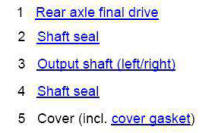
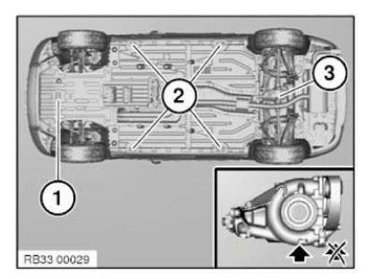
OVERVIEW OF REAR AXLE FINAL DRIVE/OUTPUT SHAFTS
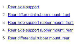
OVERVIEW OF REAR AXLE SUPPORT WITH RUBBER MOUNTS
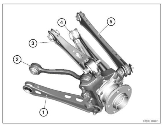
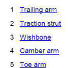
OVERVIEW OF STEERING LINKS
Raising vehicle with trolley jack
Observe the following trolley-jack-related instructions:
1. Only trolley jacks sold or approved by BMW, with a rubber plate on their mounting, may be used!
2. Trolley jacks must be regularly serviced and always checked for functional reliability before they are used!
3. Check the rubber plate on the trolley jack prior to each use, replacing if necessary.
IMPORTANT: All-wheel drive vehicles may only be raised with the stiffening plate fitted on the front axle! Raising directly on the front axle support without stiffening plate is not permissible!
WARNING: The vehicle may be raised with a trolley jack only at the following mounting point!
- Car jacking point
- Side car jacking points
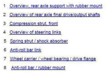
- Rear axle final drive
NOTE: It is not permitted to raise the vehicle at the rear differential cover! Risk of damage!
Jacking point (1) must be present! Align the rubber plate on the trolley jack to the jacking point (1) in such a way that there is no contact to adjacent components and that they are therefore not damaged.
REAR AXLE LAYOUT
REAR AXLE: WHEEL ALIGNMENT CHECK MUST BE CARRIED OUT AFTER THE FOLLOWING WORK
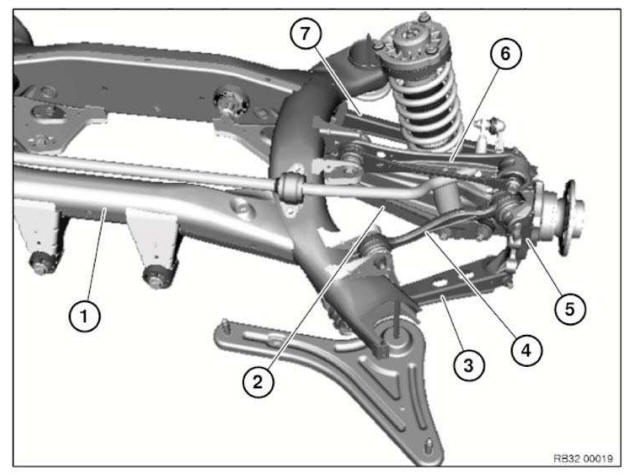
A WHEEL ALIGNMENT CHECK must be carried out after the following work:
- Release of following screw connections:
- Camber arm on rear axle support (2)
- Toe arm on rear axle support (7)
- Replacement of following parts:
- Rear axle support (1)
- Toe arm (2)
- Wheel carrier (5)
- Wishbone (6)
- Toe arm (7)
Risk of injury if oil comes into contact with eyes and skin
Danger of injury!
Contact with eyes or skin may result in injury!
Possible symptoms are:
- Impaired sight
- Irritation of the eyes
- Reddening of the skin
- Rough and cracked skin
Protective measures/rules of conduct:
- Wear safety goggles
- Wear oil-resistant protective gloves
- Observe country-specific safety regulations
First aid measures:
- Eye contact: Rinse eyes immediately with plenty of water for at least 15 minutes; if available, use an eye-rinsing bottle. If irritation of the eyes persists, consult a doctor.
- Skin contact: Wash off with soap and water immediately. If irritation persists, consult a doctor.
Safety instructions for handling oil
WARNING: DANGER OF POISONING if oil is ingested/absorbed through the skin! RISK OF INJURY if oil comes into contact with eyes and skin!
Recycling: Observe country-specific waste disposal regulations.
Measures if oil is unintentionally released:
- Personal precautionary measures: Danger of slipping! Keep non-involved persons away from the work area. Wear personal protective clothing/equipment.
- Environmental protection measures: Prevent oil from draining into drain channels, sewerage systems, pits, cellars, water and the ground.
- Limiting spread: Use oil blocks to prevent the surface spread of oil.
- Cleaning procedure: Bind and dispose of escaped oil with nonflammable absorbents.
NOTE: Do not flush oil away with water or aqueous cleaning agents.
Final drive
REAR AXLE FINAL DRIVE: ASSIGNMENT TO MODEL SERIES
Removing and installing/replacing rear differential
Special tools required:
- 33 5 206
- 33 5 200
- 33 5 120
- 33 5 125
- 33 5 123
- 33 5 121
- 33 5 124
- 33 5 126
- 33 5 122
- 33 5 127
WARNING: Danger of injury! Rear axle differential must be lashed with tensioning strap 33 5 206 to prevent it from dropping down when pressing the output shafts off.
IMPORTANT: When removing/reinstalling the rear axle final drive, both OUTPUT SHAFT RADIAL SHAFT SEALS and the circlip on both output shafts must be replaced.
After completing repair work, CHECK GEARBOX OIL LEVEL.
Necessary preliminary work:
- Remove PROPELLER SHAFT ON REAR AXLE FINAL DRIVE .
- Disconnect propeller shaft at rear axle differential.
- Release center mount.
- Tie up propeller shaft to underbody.
NOTE: Bending the propeller shaft by an excessive angle can cause premature damage to the joint/propeller shaft!
Position special tool 33 5 200 on workshop jack.
Support rear axle final drive 33 5 200 with special tool.
Lash rear axle final drive with tensioning strap 33 5 206 to special tool 33 5 200 .
IMPORTANT: Tensioning strap 33 5 206 must be pass through between output shafts and rear axle final drive cover!
IMPORTANT: Special tools 33 5 120 and 33 5 125 must be inserted in all-round slot (1) on output shaft!
Press only left output shaft out of rear axle final drive with jerking and jolting motions using special tool 33 5 123 , 33 5 121 , 33 5 124 /33 5 126 .
Here, synchronising key of bolt 33 5 122 must rest on rear axle final drive.
Installation note: Adhere to the installation sequence at the end of the document in order to prevent distortion of the rear axle final drive during installation and thereby avoid potential complaints about noise.
Slacken nut (1).
N47 only: Remove vibration absorber (2) with holder.
Installation note: Adhere to the installation sequence at the end of the document in order to prevent distortion of the rear axle final drive during installation and thereby avoid potential complaints about noise.
Lower rear axle final drive with special tool 33 5 200 .
Press (tilt) rear axle final drive on right upwards.
Feed out left output shaft in downward direction and tie up.
Swing rear axle final drive towards left side.
Press right output shaft out of rear axle final drive with jerking and jolting motions using special tool 33 5 123 , 33 5 121 , 33 5 124 /33 5 126 . Here, synchronising key of bolt 33 5 122 must rest on rear axle final drive.
Feed out output shaft and tie up.
Remove rear axle final drive.
IMPORTANT: High installation forces indicate that the output shaft spline teeth are damaged or deformed!
Check gearing and replace components if damaged.
Check dust plate (1) for damage, renew if necessary.
Circlip (2) must be replaced.
Coat highlighted contact surface (3) of output shaft with approved final drive oil.
Installation note: Insert output shaft into rear axle final drive.
Pull out assembly protection ring at lug (1) until one of the two predetermined breaking points gives.
Drive output shaft into rear axle final drive using special tool 33 5 125 33 5 127 and a rubber mallet.
Assembly sequence:
- Install rear axle final drive with workshop jack and special tool 33 5 200 in rear axle support
- Insert bolts (1) (do not tighten down)
- Insert bolt from rear and replace nut (2) (do not tighten down)
- Release tensioning strap, lower special tool 33 5 200 and move away
- Tighten down screws (1)
- Tighten nut (2)
After installation:
- Check TRANSMISSION OIL LEVEL, correct if necessary.
Replacing shaft seal(s) for output shaft(s) in rear axle final drive
Special tools required:
- 00 5 010
- 32 1 060
- 33 1 308
- 33 5 130
- 33 5 140
Necessary preliminary work:
- Remove REAR AXLE FINAL DRIVE.
Use special tools 00 5 010 and 32 1 060 /33 1 308 to remove radial shaft seal
Installing new shaft seal:
NOTE: The installation protective ring (1) serves to protect the sealing lips of the radial shaft seal (2) when installing the output shaft.
IMPORTANT: Installation protective ring (1) must not slip out of radial shaft seal!
Coat housing plate flange of new shaft seal with approved rear differential oil. Drive in radial shaft seal as far as it will go with following special tools (depending on rear axle final drive/outer diameter).
- 33 5 130
- 33 5 140
Remove special tool.
Open installation protective ring (1).
IMPORTANT: High installation forces indicate that the output shaft spline teeth are damaged or deformed! Check gearing, replace damaged components if necessary.
Check dust plate (1) for damage, renew if necessary.
Replace circlip (2).
Coat highlighted contact surface (3) of output shaft with approved final drive oil.
Insert output shaft into rear axle final drive.
Pull out assembly protection ring at lug (1) until one of the two predetermined breaking points gives.
After installation:
- Check FINAL DRIVE OIL LEVEL, correct if necessary.
 General information on high temperature multi-purpose grease
1.0 GENERAL INFORMATION ON HIGH TEMPERATURE MULTI-PURPOSE
GREASE
High temperature multi-purpose grease consists of a lithium complex soap in a min ...

Other materials:
BMW X3 (F25) Service & Repair Manual > Driveline+Axles: Specified grease
GREASE FOR PROPELLER SHAFT (FLEXIBLE COUPLING (RUBBER DOUGHNUT) CENTER
BEARING AND SPLINE END)
Use one of the following greases for greasing the propeller shaft center bearing or locating pin of the
transmission output flange and the splines of the propeller shaft spline end.
GREASE FOR PROPELLE ...
