BMW X3 (F25) Service & Repair Manual: Ignition coil
Replacing ignition coils (N20)
Necessary preliminary tasks:
- Read out the fault memory of the DME control unit.
- Check stored fault messages and process procedure.
- Switch off ignition.
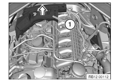
- Remove ACOUSTIC COVER
IMPORTANT: Ignition coils must not be contaminated by fuel.
The resistance of the silicone material is reduced significantly by contact with fuel, which may cause the ignition coil to fail! The silicone tube of the spark plug connector is coated with talc to reduce the pulling forces.
The silicone tube must NOT be oiled or greased. This would greatly reduce the durability of the silicone material, which can lead to a malfunction of the ignition coil.
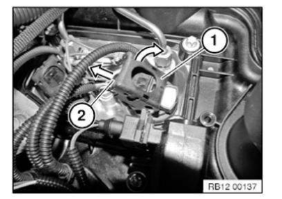
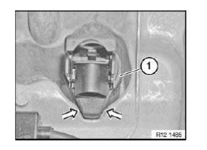
Unlock plug catch (1) of ignition coil (2) and disconnect plug.
Ensure that cables are not crushed or damaged.
Repair damaged cable.
Pull ignition coil (2) up and out.
NOTE: There is a possibility that the silicone tube will tear and therefore be destroyed.
This procedure is applicable to all ignition coils.
Installation note:
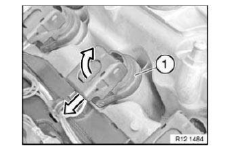
Position the ignition coil and gently push it to the limit position, if necessary by twisting it back and forth slightly. Then check anti-twist lock.
The rubber cap must completely surround the sealing collar of the cylinder head cover.
NOTE: If rubber parts are squashed, the ignition coil can slip out again during engine operation.
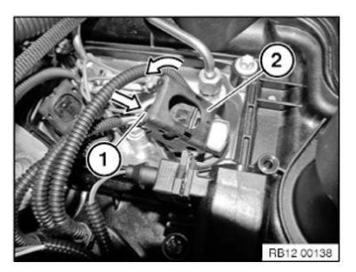
Push connector (1) with connector catch (2) open onto ignition coil.
Carefully close connector catch (2) in direction of arrow.
Ensure that cables are not crushed or damaged.
Repair damaged cable.
The connector must be positioned on the counter piece with hardly any gaps when the locking lever is being closed. In the process, the cheeks of the lever are positioned inside the counter piece.
NOTE: The locking lever can become deformed if it is not installed correctly. This means that there is no longer a safety lock on the plug connection. As a result, the connector can slip out during engine operation (loose contact, misfiring).
The connector catch must snap into place without great effort.
NOTE: Clear diagnostic fault entries from fault memory.
Assemble engine.
Replacing ignition coils (N55)
Necessary preliminary tasks:
- Read out the fault memory of the DME control unit.
- Check stored fault messages and process procedure.
- Switch off ignition.
- Remove IGNITION COIL COVER.
- Remove CLEAN AIR PIPE .
IMPORTANT: Ignition coils must not be contaminated by fuel.
The resistance of the silicone material is reduced significantly by contact with fuel, which may cause the ignition coil to fail! The silicone tube of the spark plug connector is coated with talc to reduce the pulling forces.
The silicone tube must NOT be oiled or greased. This would greatly reduce the durability of the silicone material, which can lead to a malfunction of the ignition coil.
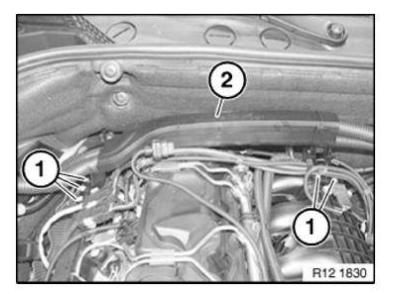
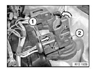
Release screws (1).
Slide cable channel (2) to one side.
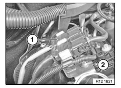
Release oxygen sensor connector (1) from bracket.
Release screw (2).
Put cable clip aside.
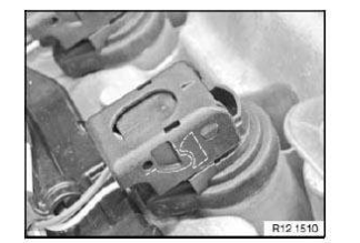
Unlock plug catch (1) of ignition coil (2) and disconnect plug.
Ensure that cables are not crushed or damaged.
Repair damaged cable.
Pull out the ignition coil (2) slowly in a smooth upwards movement.
NOTE: There is a possibility that the silicone tube will tear and therefore be destroyed.
This procedure is applicable to all ignition coils.
Installation note:
Position the ignition coil and gently push it to the limit position, if necessary by twisting it back and forth slightly. Then check anti-twist lock.
The rubber cap must completely surround the sealing collar of the cylinder head cover.
NOTE: If rubber parts are squashed, the ignition coil can slip out again during engine operation.
Push connector (1) with connector catch (2) open onto ignition coil.
Carefully close connector catch (2) in direction of arrow.
The connector catch must snap into place without great effort.
Ensure that cables are not crushed or damaged.
Repair damaged cable.
The connector must be positioned on the counter piece with hardly any gaps when the locking lever is being closed. In the process, the cheeks of the lever are positioned inside the counter piece.
NOTE: The locking lever can become deformed if it is not installed correctly. This means that there is no longer a safety lock on the plug connection. As a result, the connector can slip out during engine operation (loose contact, misfiring).
NOTE: Clear diagnostic fault entries from fault memory.
Assemble engine.
Replacing ignition coils (N52T)
Necessary preliminary tasks:
- Read out the fault memory of the DME control unit.
- Check stored fault messages and process procedure.
- Switch off ignition.
- Remove IGNITION COIL COVER .
IMPORTANT: Ignition coils must not be contaminated by fuel.
The resistance of the silicone material is reduced significantly by contact with fuel, which may cause the ignition coil to fail! The silicone tube of the spark plug connector is coated with talc to reduce the pulling forces.
The silicone tube must NOT be oiled or greased. This would greatly reduce the durability of the silicone material, which can lead to a malfunction of the ignition coil.
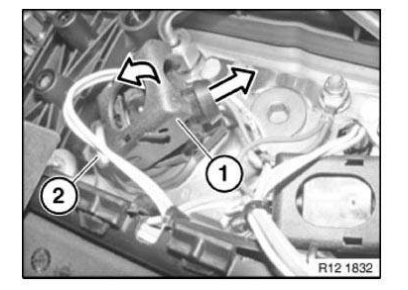
Release positive battery cable (1) from holder (3) and lay to one side.
Unfasten screws (2).
Remove bracket (3).
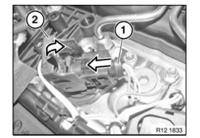
Unlock connector fastener of ignition coil (1) and disconnect connector.
Slowly pull the ignition coil (1) up and out without jerking it.
NOTE: There is a possibility that the silicone tube will tear and therefore be destroyed.
This procedure is applicable to all ignition coils.
Installation note:
Position the ignition coil (1) and gently push it to the limit position, if necessary by twisting it back and forth slightly. Then check anti-twist lock.
The rubber cap must completely surround the sealing collar of the cylinder head cover.
NOTE: If rubber parts are squashed, the ignition coil can slip out again during engine operation.
Installation note:
Push connector (1) with connector catch (2) open onto ignition coil.
Carefully close connector catch (2) in direction of arrow.
The connector must be positioned on the counter piece with hardly any gaps when the locking lever is being closed. In the process, the cheeks of the lever are positioned inside the counter piece.
NOTE: The locking lever can become deformed if it is not installed correctly. This means that there is no longer a safety lock on the plug connection. As a result, the connector can slip out during engine operation (loose contact, misfiring).
Installation note:
The connector fastener must snap into place without great effort.
NOTE: Delete fault memory.
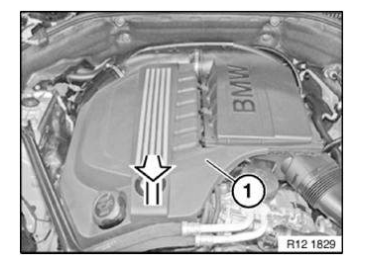
REMOVING AND INSTALLING/REPLACING IGNITION COIL COVER (N55)
Pull ignition coil cover (1) off of rubber mounts and remove in direction of travel.
REMOVING AND INSTALLING/REPLACING REAR IGNITION COIL COVER (N55)
Necessary preliminary work:
- Remove CLEAN AIR PIPE .
Pull off ignition coil cover (1) upward and remove.


Other materials:
BMW X3 (F25) Service & Repair Manual > Transmission: Automatic transmission fluid for zf-transmission
GA8HP45Z / GA8HP50Z / GA8HP70Z / GA8HP90Z / GA8P70H / GA8P75H /
GA8HP75Z
14.0 AUTOMATIC TRANSMISSION FLUID FOR ZF-TRANSMISSION
GA8HP45Z / GA8HP50Z / GA8HP70Z / GA8HP90Z / GA8P70H / GA8P75H /
GA8HP75Z
NOTE:
The automatic transmissions have a life-time oil filling. These transmissions
require no oil change for their entire service life.
The approved lifetime fluid ...
