BMW X3 (F25) Service & Repair Manual: Body repair instructions
- Contents of body, general
- Blind rivet
- Bonding on painted/primed surfaces
- Bonding steel on steel
- Checklist for front seat
- Corrosion protection
- Emc screws
- Frame alignment control dimensions, body
- Gap dimensions, body
- General instructions on paintwork
- General notes for labelling with adhesive films
- Grinding aluminum components
- Grinding steel parts
- Handling airbags and restraint systems
- Handling electrical system and electronics
- Information on hazards
- Information on metal filler
- Information on using cleaning agent/paints (personal protection equipment)
- Information on vehicle protection
- Installation solution for straight shank/hexagon rivet nut
- Installing a cavity sealing with 2-component pu cavity foam
- Installing cavity sealing (expanded)
- Installing cavity sealing (not expanded)
- Materials science
- Notes for repairing aluminum rims
- Notes on adhesive K1
- Notes on adhesive K2
- Notes on adhesive K3
- Notes on adhesive K4
- Notes on adhesive K5
- Notes on adhesive K6
- Notes on handling the high pressure cleaner
- Notes on repairing threads
- Notes on the water drain hose of the slide/tilt sunroof
- Notes on using temperature-controlled infra-red radiators
- Opening bonded connections
- Opening rivet connections
- Opening welded connections
- Overview of adhesive cartridge guns
- Position of shaped parts for cavity sealing
- Punch rivets
- Quality standard
- Reinforcement plate (bonded)
- Reinforcement plate with stud bolt (bonded)
- Releasing bonded folded seam connections
- Repair methods, repair stages 1
- Repair solution for straight shank/hexagon rivet nut
- Repair techniques, repair stage 2
- Repair techniques, repair stage 3
- Repairing clips for roof strip
- Repairing headlights
- Repairing plastic components
- Replacement parts standards
- Replacing blind rivets
- Safety at work
- Safety information for working on vehicles with automatic engine start-stop function (MSA)
- Safety instructions for handling magnets
- Separating cut determination with a template
- Soldering steel components
- Spot-weld bonding steel components
- Spray gun for cavity sealant
- Stamping vehicle identification number (needle stamping unit)
- Straightening aluminum component on the outer skin
- Straightening aluminum components in structure
- Straightening steel components in the structure
- Straightening steel components on the outer skin
- Touching up paintwork damage
- Use of materials in outer skin
- Vehicle identification number, general
- Welding in reinforcement plate (sheet steel)
- Welding steel components
- Working with 2-component PU cavity foam
- Workshop equipment (BMW and mini vehicles)
Contents of body, general
Before starting repair work
- BMW i
Checking the body for damage (e.g. following an accident)
General notes
- Quality standard .
- WORKSHOP EQUIPMENT
Safety regulations
- SAFETY AT WORK
- Information on VEHICLE PROTECTION
- INFORMATION ON HAZARDS
Material/new part
- MATERIALS SCIENCE
- EXPENDABLE MATERIALS
- USE OF MATERIALS in outer shell
Handling components
- ELECTRICAL SYSTEM, electronics and fibre optics
- FLOOD DAMAGE
- Passive safety.
- CHASSIS, SUSPENSION AND STEERING
- Retractable hardtop
- Vehicles with hybrid/electric drive
- SEATS/SEAT BELTS
- WHEEL RIM REPAIRS
- HEADLIGHT REPAIRS
Body dimensions
- FRAME DIMENSIONS
- GAP DIMENSIONS
Cavity sealing
- Installation of shaped parts .
- POSITION OF SHAPED PARTS
Vehicle identification number
- GENERAL VEHICLE IDENTIFICATION NUMBER
- ENTER VEHICLE IDENTIFICATION NUMBER
Repair method
- REPAIR STAGE 1A
BMW/MINI/BMW i
- Replacement of screwed-on components
- REPAIR STAGE 1B
BMW/MINI/BMW i
- Repairs to outer skin
- REPAIR STAGE 2
BMW/MINI
- Bonding and riveting
- Welding using a MAG welder
- without straightening bench
BMW i
- Repairs to life module
- Repairs to drive module
- without straightening bench
- REPAIR STAGE 3
BMW/MINI
- Bonding and riveting
- Welding using a spot welding system
- with a straightening bench
BMW i
- Repairs to life module
- Repairs to drive module
- with a straightening bench
Corrosion protection
- GENERAL INFORMATION
Paint
- GENERAL INFORMATION
- INFORMATION/WARNING LABELS
- Separate component and sectional paintwork
NOTES ON THE REPAIR TECHNIQUE USED IN THE MAIN GROUP 41
Two different repair techniques are used in body repair.
These are welding and bonding/riveting.
If the repair instructions do not specify a repair technique, then welding must always be used.
The bonding/riveting repair technique is always described in detail in the repair instructions.
Quality standards must be met.
Blind rivet
1.0 Recommended tools and equipment
- Blind riveting tongs
- Rivet head extension
Setting blind rivets:
- Refer to repair instructions for rivet size.
- Position bore holes for blind rivets in accordance with specification in repair instructions. If necessary, carry over the positions of the blind rivets to the new part.
- Drill holes that exceed the outer diameter of the blind rivet (example Ø 4.2 mm with 4 mm blind rivet and Ø 6.8 mm with 6.5 mm blind rivet).
- The edge of the hole must even on both sides. If necessary, sand down and even out surfaces (e.g. edges of punch rivet connections). Deburr bore holes.
- APPLY ADHESIVE.
- Insert blind rivet. If necessary, remove adhesive that has emerged.
Position blind rivet tool vertically. Use rivet head extension if accessibility is poor.
- Rivet blind rivet with blind rivet tool. In the meantime clean rivet head if dirty with adhesive. Risk of damage to rivet head by penetrating adhesive.
- Seal blind rivet with SEALANT D1 (risk of corrosion).
- Seal cavities after work on vehicle paintwork on with CAVITY PRESERVATION (risk of corrosion).
Bonding on painted/primed surfaces
IMPORTANT: These repair instructions apply only to components of the outer skin and not to structural components.
These include roof outer skin, tail panel, rear side panels and components of the luggage compartment floor.
Follow the vehicle-specific repair instructions.
Only the repair method described there must be used! Conform with safety regulations .
Overview of topics:
- Equipment
- Expiry date of consumables
- Preparation of surface
- Bonding coat
- Hardening times
- Subsequent treatment
- Disposal of adhesive
1.0 Equipment
- CLEANING AGENT R1
- ADHESIVE K5
- CARTRIDGE GUN
2.0 Expiry date of consumables:
- Glue cartridge is marked with a date.
- Do not use adhesive after this date.
3.0 Preparation of surface:
3.1 Preparation of the surface on the vehicle (series status):
- Establish a level bonding surface (e.g. grinding).
- Do not sand primed bonding surfaces.
If the bonding surface is painted in the vehicle colour, the paint must be completely sanded off.
- If necessary, pre-clean
bonding surfaces with cavity sealing wax remover.
Clean bonding surfaces with cleaning agent R1.
- Allow cleaned surfaces to dry for approx. 5 min.
Bonding surfaces must be completely dry.
3.2 Preparation of the surface on the vehicle (replacement of a bonded component):
- Remove adhesive residue completely from vehicle. Remove all old reinforcement plates if necessary (e. g. rear side panel).
- Do not prime in the area of the bonding surfaces! Adhesive
insufficiently bonds to primer.
If priming is needed after straightening work, cover the bonding surfaces.
- If necessary, pre-clean
bonding surfaces with cavity sealing wax remover.
Clean bonding surfaces with cleaning agent R1.
- Allow cleaned surfaces to dry for approx. 5 min.
Bonding surfaces must be completely dry.
3.3 Preparation of surface on new part:
- Do not remove primer on new part.
Do not grind/sand bonding surfaces.
- Clean bonding surfaces with cleaning agent R1.
- Allow cleaned surfaces to dry for approx. 5 min.
Bonding surfaces must be completely dry.
4.0 Adhesive application:
- Processing temperature of glue cartridge 18 ºC 30 ºC.
- Object temperature, vehicle and new parts, at least 15ºC.
- Do not use an air-powered cartridge gun.
- Insert glue cartridge into cartridge gun, remove cap and allow both adhesive components to emerge. Strip adhesive components uniformly and attach mixing tube.
- Allow approx. 10 cm of mixed adhesive to emerge and then apply the mixed adhesive first on one side of the bonding surface.
- After applying the adhesive, check whether an adhesive component has emerged at the back of the glue cartridge. If yes, break off the bonding procedure. Clean new part. Use new glue cartridge.
- Pot life of mixed adhesive approx. 2 h. A change of mixer is necessary only if no material has flowed through the mixer for a period of 30 min.
- Join components and secure in position.
- Remove excess adhesive.
5.0 Hardening times:
- Do not move the vehicle before the adhesive has hardened.
Check the degree of hardness of the adhesive with a fingernail.
If the adhesive cannot be pressed in any further with a fingernail, the vehicle may be moved (without engine force) for further processing applications (e.g. painting).
- Vehicle strength for driving applications is achieved after:
48 h at an object temperature of at least 15 ºC (corresponds to approx. 18
ºC room
temperature).
Or 1 h in the spray booth (spray booth temperature 80 ºC/object temperature 60 ºC).
- When using radiant heaters, make sure that the object temperature does
not exceed 85 ºC.
Excessively high temperatures will destroy the adhesive.
- Remove contamination caused by adhesive residue immediately.
Hardened adhesive can only be removed mechanically.
6.0 Subsequent treatment:
- Reseal areas which are cavity-sealed as standard.
7.0 Disposal of adhesive:
- Hardened adhesive is disposed of as normal waste.
- Empty glue cartridges are disposed of as normal waste.
- Non-hardened adhesives and mixtures of adhesive and solvent and the like must be disposed of as hazardous waste.
These regulations apply to the Federal Republic of Germany.
For other countries, comply with the (possibly differing) nationally applicable regulations.
Bonding steel on steel
IMPORTANT: These repair instructions apply to structural components.
Such components include engine supports, A-pillars, B-pillars, etc.
Follow the vehicle-specific repair instructions. Only use the repair procedures described there.
Conform with safety regulations .
INFORMATION ON HAZARDS!
Overview of topics:
- Equipment
- Preparing the surface
- Bonding coat
- Hardening times
- Subsequent treatment
1.0 Equipment
- Sandpaper
- CLEANING AGENT R1
- ADHESIVE K1
- CARTRIDGE GUN
2.0 Preparing the surface:
- For better adhesion, remove oxide film and paint from the adhesive areas with a stainless steel wire brush or special sandpaper.
- Clean bonding surfaces with cleaning agent R1.
- Allow cleaned surfaces to dry for approx. 5 minutes.
- Bonding surfaces must be completely dry.
3.0 Adhesive application:
- Processing temperature of glue cartridge 18 ºC - 30 ºC.
- Object temperature, vehicle and new parts, min. 15ºC.
- After applying the adhesive, check whether an adhesive component has emerged at the back of the glue cartridge. If yes, break off the bonding procedure. Clean new part. Use new glue cartridge.
- Join components and secure in position.
- Remove excess adhesive. Do not use solvent cleaning agents.
4.0 Hardening times:
- Refer to NOTES REGARDING ADHESIVE K1
5.0 Subsequent treatment of bonding surfaces:
- Protect the repair area with cavity sealant.
Checklist for front seat
| Event | Check | Action | |
| Has at least one belt tensioner and/or one side airbag been activated? | Yes | Check 1 (when installed):
Check all seat adjustment options of
both front seats. There must be no stiff movement, sticking or other functional problems or noises across the entire adjustment range of all the seat adjustment options. Check head restraints for damage. Check crash-active headrest for activation. Only 2-door model: Check backrest lock. Backrest must unlock and lock easily without any great physical effort. |
If components are OK with
regard to checks 1 and 2, only replace activated belt
tensioner or side airbag. Otherwise, replace faulty parts on the seat/body. Replace belt tensioner, seat belt and, if necessary, side airbag. |
Check 2 (when dismounted):
Check for deformation/damage on the
following components:
Check for visible damage or deformation. |
|||
| No | Check all adjustment options of the head
restraints. Check crash-active headrest for activation. |
Replace faulty parts. | |
| Only seat with integrated seat belt: | |||
| Does the backrest indicator light turn on when the backrest is locked and also when the backrest is shaken? | Yes | Check microswitch of backrest lock and renew if necessary. Check electrical lines and repair if necessary. | If there is still a fault, replace the entire seat |
| No | No further action necessary. | Â | |
Corrosion protection
NOTE: Following repairs, the corrosion protection work already begins with the correct removal of the underbody protection, anti-drumming layer and seam sealing in the repair area.
The PRODUCTS RECOMMENDED by BMW are optimized with regard to corrosion protection.
1.0 Removing and applying sealant:
1.1 Removing sealant:
IMPORTANT:
- Do not burn off PVC material (sealant) with an autogenous torch or similar or heat to temperatures above 180 ºC. This would generate highly corrosive hydrochloric acid and release harmful vapor.
- The new sealant does not adhere appropriately to burnt polyvinyl chloride material and hence subsequent rust creep is possible.
Remove PVC material with a rotating steel brush, or heat PVC to maximum 180 ºC with a hot air blower and scrape off with a spatula.
Remove PVC material with a rotating steel brush, or heat PVC to maximum 180 ºC with a hot air blower and scrape off with a spatula.
1.2 Applying sealant:
Prime and seal all weld seams that are sealed with sealant in original condition immediately after repair work. Replace damaged or removed anti-drumming layers.
NOTE: Required spray gun for sealant (order number 81 49 0 300 887).
Seal blind rivet with SEALANT (risk of corrosion).
2.0 Basics of cavity preservation:
Apply cavity preservation after all body repairs.
Concluding cavity preservation is the most important part of all corrosion protection measures.
Use the cavity protection spray only for smaller-scale straightening work where the parts in question are easily accessible. Use the PRESSURE CUP GUN for all other repairs. Cavity protection agent is available in different container sizes.
Use the relevant sensors with tubes for the different cavity areas.
IMPORTANT: Incorrectly performed cavity protection can, especially in the case of steel/aluminum joints, give rise to a non-calculable product liability and safety risk.
The best repair is worth nothing if the subsequent cavity protection measures are not conscientiously carried out.
2.1 Cavity preservation of steel parts:
New doors and lids must be sealed with cavity protection agent after being painted.
New sheet-metal parts or cavities, weld seams and folds formed by new sheet-metal parts must be sealed with cavity protection agent after being painted.
The cavities affected must be sealed with cavity protection agent after all straightening work.
2.2 Cavity preservation of aluminum parts:
New doors, lids and side panels made of aluminum are not sealed with cavity protection agent.
After all straightening work on aluminum components, the cavities affected must be sealed with cavity protection agent after being painted.
After all welding work (E52 only) on aluminum components, the cavities affected must be sealed with cavity protection agent after being painted.
Cavities, seams and folds formed from new sheet metal parts or extruded profile must be sealed with cavity protection agent after being painted.
Emc screws
(EMC = Electro-Magnetic Compatibility)
1. Purpose:
- EMC SCREWS are used in the Bonding/Riveting repair method to re-establish bonding transition.
- They assume the function of welded joints, which ensure transition to ground between the individual components.
- The punch or blind rivets used in the repair do not guarantee permanent bonding transition between the individual components!
- The EMC screws ensure the operational reliability and safety of the electrical/electronic components following repairs!
2. Procedure, aluminum front end:
- Each welded joint which is opened must be replaced by at least 2 EMC screws.
- Position the 2 screws on the flange on which the weld seam has been separated. In the event of partial replacement, position the screws in the area of the component overlap.
- In the case of repairs using partial replacement, the number of EMC screws described in the repair instructions must be fitted.
- Drill holes to a diameter of 4.2 mm and insert screws.
- Seal EMC screws with PU sealing material (risk of corrosion).
3. Procedure, steel body:
- Install the number of EMC screws described in the repair instructions.
- Drill holes to a diameter of 4.2 mm and insert screws.
- Seal EMC screws with PU sealing material (risk of corrosion).
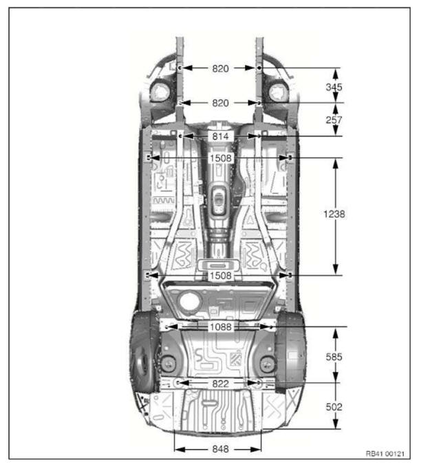
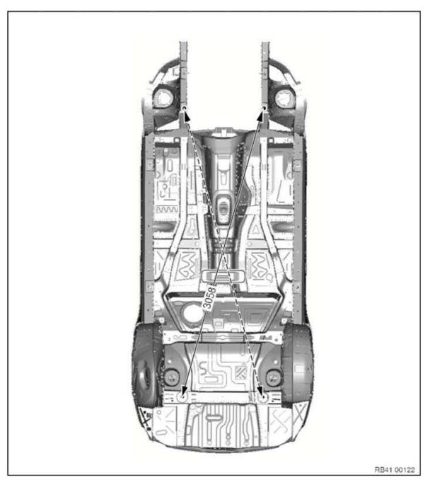
Frame alignment control dimensions, body
Dimensions in mm.
Measurement tolerances:
- ≤ 1000 mm Â+- 1.5 mm
- ≥ 1000 mm Â+- 2.5 mm
The control points shown serve to check the body and the set of attachments.
The specified dimensions/measurements refer to the center point of the bore/screw.
Underbody view 1
Underbody view 2
Top view, front end
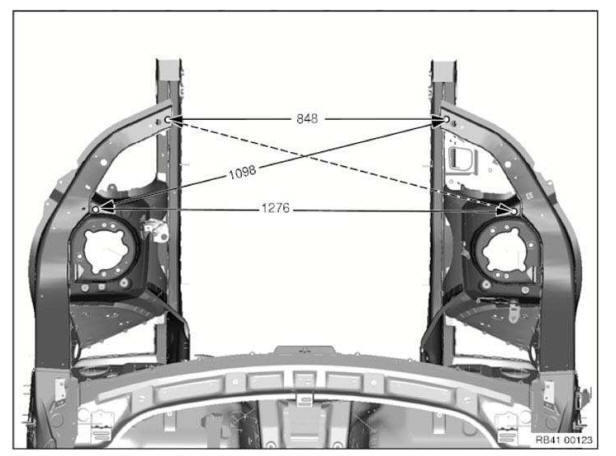
The specified dimensions refer to removed assemblies.
View, B-pillar
Measurement a=1556 mm between screw-on points of door brakes.
Gap dimensions, body
The dimensions specified in this information are applicable at an object temperature of 20 ºC. The aim of adjustment is to achieve a uniform gap.
Symmetry of the gaps between left and right sides of the vehicle has top priority.
The door gaps must not deviate between the front and rear door gap by more than 1.0 mm.
No gap dimension are specified for components which cannot be adjusted.
Dimensions in mm
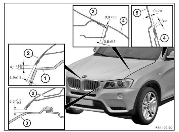
- Panel, bumper, front
- Headlight

- Rear door
- Rear side walls
General instructions on paintwork
The marked area serves as reference value for paintwork. This area may differ from the illustration for technical painting reasons.
Touching-up areas are taken into account.
Special procedure for matte paintwork: Matte paintwork cannot be touched up since the painted surface cannot be polished.
General notes for labelling with adhesive films
In the event of a repair the adhesive films must be partially or completely replaced. The basic procedure for all areas of the vehicle is described below.
In addition, vehicle-specific repair instructions are available.
1. Preparation: Wash and dry vehicle. Rework with compressed air as required in area of joints.
Clean complete component surface with glass cleaner (BMW part number 83 12 0 396 775). Also clean the inside of the component in areas, in which adhesive films are applied.
Only carry out repair work with clean hands!
IMPORTANT: Labels can only be applied to recently painted components after a waiting period of 2 weeks . The paint hardening is only fully completed after this time.
2. Procedure for applying labels: All adhesive films in the repair kit are marked with numbers. Prepare the required plastic films prior to start of repairs.
The templates included in the repair kit assist orientation. A straight line running over the different components is the top priority.
Pull off the templates positioning of the adhesive films.
Only throw away templates after completion of all repair work, as some templates are used several times.
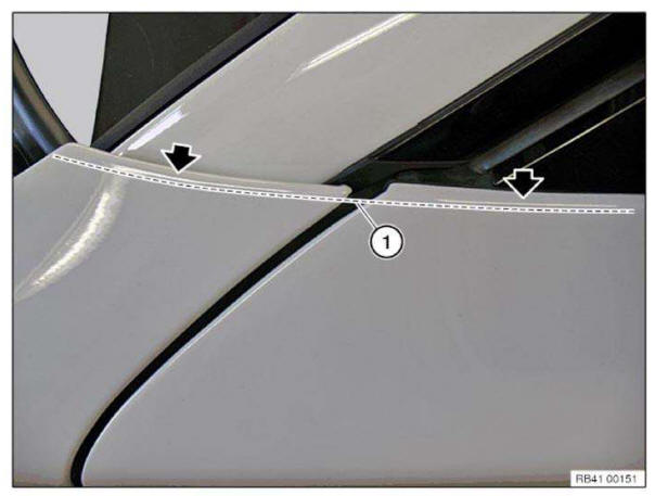
Templates are always applied along the light edge (1). The light edge is the reflection of the light source in radius (see arrow).
Roughly align the adhesive film using a template.
For large adhesive films, pull off the first 20 cm of protective film and fold back the edge.
Align and lightly press down the adhesive film. Use only one finger for this and not the entire hand so that air pockets are unable to form under the adhesive film.
Pull off the remaining protective film and press down the adhesive film from front to rear and from inside to outside.
If faults are made in applying the adhesive film, it can be pulled off and repositioned several times. When no further corrections have to be made, use a squeegee to press down the adhesive film firmly from inside to outside.
Lay protruding ends of the adhesive film around the component edge and press down firmly.
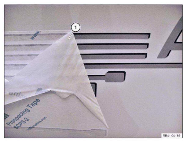
Carefully pull off backing film (1) at an acute angle.
Grinding aluminum components
1.0 Recommended tools and equipment
Grinding work on the outer skin:
-
To carry out grinding work by hand or machine, you must use the recommended tools and
equipment.
The workbay can be cleaned with conventional extractor systems (low dust concentration).
Grinding work on the structure (except Z8):
-
To carry out grinding work by hand or machine, you must use the recommended tools and
equipment.
The workbay can be cleaned with conventional extractor systems (low dust concentration).
Z 8 Spaceframe structure:
-
To carry out machine grinding on the structure, you must use the recommended device with
grinding dust extractor facility.
The workbay must be cleaned with the recommended explosion-proof extractor system.
High dust concentration, explosion hazard!
2.0 Grinding outer skin and structure
Do not use any abrasives (grinding wheels, paper, etc.) which contain iron (risk of corrosion).
Always replace abrasives which have already been used to treat steel (risk of corrosion).
Use stainless steel wire brushes only (risk of corrosion).
Reduce speed of grinding machines. Excessive speeds cause a smearing effect.
Do not use coarse abrasive grains (only ≥ 80).
Do not grind notches into the material (risk of cracking).
Do not grind the material thin.
Grinding steel parts
1.0 Recommended tools and equipment
- Tools are recommended for manual grinding work.
- Machines/equipment are recommended for machine grinding work.
2.0 Grinding outer shell and structure
Always replace abrasives which have already been used to treat aluminum (risk of corrosion).
Do not grind the material thin.
Handling airbags and restraint systems
1.0 Airbags and restraint systems
- In the case of vehicles with airbags and restraint systems observe the relevant SAFETY INSTRUCTIONS .
-
When straightening work is carried out on the body there is a risk of airbags being accidentally
activated when the battery is connected.
Because of this risk the battery ground cable must be DISCONNECTED prior to all repair work on the body.
HANDLING COMPONENTS AFTER FLOOD DAMAGE
Flood damage can occur if the permissible fording depth of a vehicle is exceeded. Ingress of water can cause damage to the engine (water shock) or components.
Because dirt particles generally enter into the component with the water (e.g. starter motor, wiring harness), the components need to be thoroughly inspected.
Residual moisture in the components leads to corrosion (increased contact resistance in the component), which can lead to a component failure at a later time.
If water ingress into the electrical components cannot be ruled out, it is recommended to replace the component to ensure correct functioning through the vehicle lifetime.
Handling electrical system and electronics
1.0 Battery
- Explosion hazard in the vicinity of the battery during welding and grinding work. The battery must be REMOVED .
2.0 Control units
- Control units with visible mechanical damages and/or electrical damages caused by accidents must be replaced.
- The following risks exist when the battery is connected:
- Damage to control units resulting from welding work on the body or a line short circuit.
- Accidental activation of airbags during straightening work on the body.
Because of these risks the ground cable must be DISCONNECTED prior to all repair work.
- Control units are designed for a temperature of 65 ºC. The temperatures in a spray booth do not pose any problems. If a vehicle is in the spray booth at a displayed temperature of 80ºC, the actual temperature of the vehicle is ≤ 60 ºC (object temperature).
- Protect control units against the influence of heat >65 ºC (e.g. during welding and drying work with infrared beams or hot air blowers).
3.0 Electrical wires and wiring harnesses
- Protect electrical wires and wiring harnesses against damage (e.g. during straightening and grinding work).
- Protect electrical wiring and wiring harnesses against the influence of heat >65 º C (e.g. during welding and drying work with infrared beams or hot air blowers).
- Do not kink electrical wiring.
4.0 Optical fibres
- Follow instructions for handling OPTICAL FIBRES .
Information on hazards
1. Aluminum
| Hazards/effects | Measures/regulations |
| Repair stage 1 and 2: No hazards/effects | none |
Repair stage 3: (Welding - only E52)
|
|
|
|
2. Carbon
| Hazards/effects | Measures/regulations |
| Repair stage 1: No hazards/effects | none |
Repair stage 2 and 3:
|
|
|
|
Information on metal filler
IMPORTANT: Note the following information before starting to apply metal filler!
- Country-specific safety and industrial safety regulations
- Material safety data sheet of manufacturer
- Processing instructions on the packaging
Storage: Dry at 15ºC to 25 ºC.
Shelf life: The packaging is marked with a date.
Do not use the metal filler after this date.
Surface pre-treatment: Grind surface to a metallic bright-finish. The surface must be clean, dry and free from grease.
Clean the surface with a cleaning agent R1 and let it vent for 2-3 minutes.
Processing: The working temperature of the metal filler must be at least 18ºC.
- Metal filler
- Hardener
NOTE: The mixture ratio refers to the volume.
Mix metal filler in mixture ratio of 5:2. Mix components thoroughly and free of pores.
IMPORTANT: Do not stir components. Danger of air pockets in metal filler!
Working life of the metal filler is approx. 45 minutes.
Applying filler: Apply pressure to apply a thin layer of metal filler. Carefully coat all edges in gaps with filler.
Then fill gap completely with filler. Apply filler with about 30% excess because the filler will significantly shrink during hardening. A second application of metal filler is not possible due to poor adhesion.
IMPORTANT: Use a narrow spatula to fill the gaps. Apply the filler in one draw if possible. Danger of formation of pores in gaps!
No restrictions related to the layer thickness.
Hardening time: The metal filler must be hardened using a short-wave infrared heater.
- 10 minutes at 50 ºC - pre-hardening (avoid formation of bubbles/blisters and pores)
- 10 minutes at 75 ºC - 1st stage hardening
- 10 minutes at 85 ºC - 2nd stage hardening (avoid material shrinkage)
IMPORTANT: In the first 10 minutes, the temperature of 50ºC may not be exceeded. In contrast, a temperature that is too low may be equalized by extending the time.
NOTE: When the heater is used for the first time, the distances that match the temperature must be determined. Switch the heater on and change the distance until the surface temperature of the metal filler no longer changes for a period of 2 minutes. Measure the temperature with a temperature gauge. When optical temperature gauges are used (Epsilon value 0.92-0.95), the heater must be switched off briefly during the measurement. Record the measurement
Post-processing
WARNING: When grinding, wear a fine dust mask with particulate filter P2-P3!
After cooling, the metal filler can be machined.
Pores and faulty spots that become visible after grinding the surface must be closed with polyester filler (BMW Colour system).
Special procedure for pores: Use a Ø4.2mm drill. Turn the drill by hand to expand the pores in v shape. by t Fill cavities with polyester filler.
Paintwork: Perform paintwork according to the specifications in the painting handbook.
IMPORTANT: When using temperature-controlled infrared radiators, damage to adhesive bonds, paint and vehicle components can occur when drying spatula and filler.
The temperature sensors in the infrared radiator only operate reliably on large, even surfaces.
On small surfaces such as C-pillars or sills, often only a colder, adjacent area is measured.
This leads to actual surface temperatures of up to 130ºC, even if only 70ºC is set on the infrared radiator.
When the rear side walls are partially replaced by bonding and riveting, these high temperatures can lead to a visible pattern in the area of the joint.
Remedy: Check the surface temperatures on small component surfaces during the drying process with an external temperature sensor.
The general rule is: The surface temperatures must not exceed 85ºC.
Metal filler disposal: Hardened metal filler is disposed of as normal waste.
Empty packaging is disposed of as normal waste.
Non-hardened metal filler and mixtures of metal filler with solvent and the like must be disposed of as hazardous waste.
These regulations apply to the Federal Republic of Germany.
For other countries, comply with the (possibly differing) nationally applicable regulations.
Information on using cleaning agent/paints (personal protection equipment)
WARNING: Use of cleaning agents/paints not compliant with instructions can cause serious injuries or burns! Handling cleaning agents/paints can trigger allergic skin and respiratory reactions!
IMPORTANT: Observe following instructions:
- Store cleaning agents/paints only in a secure cabinet.
- Keep cleaning agents/paints away from naked flames and other sources of ignition.
- Protect cleaning agents/paints from high temperatures and direct sunlight.
- Always keep an eye douche on hand, change the water regularly (once a month).
IMPORTANT: Observe following instructions before use:
- Manufacturer's instructions (on container/packaging)
- Hazard warnings (on container/packaging)
- Manufacturer's instructions on package insert
- Material safety data sheet of manufacturer
- National market regulations
IMPORTANT: Observe following instructions during use:
- Do not eat, drink or smoke while working with these products.
- Avoid direct contact with skin and eyes.
- Wear personal protective clothing/equipment.
- Ensure that all enclosed areas are well ventilated or extract fumes directly.
- Immediately change working clothes soiled with cleaning agent/paint.
- After finishing work, wash your hands and apply protective skin cream.
IMPORTANT: Follow hazard warnings and wear personal protection equipment!
First Aid:
-
If product comes in contact with eyes, immediately flush with running water for about 10 - 15 minutes.
Seek the advice of eye specialist.
- In the event of skin contact and where applicable an allergic skin reaction, clean the affected areas immediately with soap and water and then apply silicone-free skin cream. Seek advice of physician.
- If an adhesive product is swallowed, rinse mouth/parts of mouth thoroughly with running water. Drink 1- 2 glasses of water. Do not induce vomiting. Consult a doctor.
- After inhaling vapors ensure ample supply of fresh air. Keep calm, keep respiratory tracks clear and call doctor.
Recycling: Dispose of cleaning agents/paints in a professional manner! Observe national/country-specific disposal regulations.
Information on vehicle protection
- Vehicle parts located in the repair zone or threatened by heat, sparks or dust, must be removed or covered.
IMPORTANT: Do not use flammable or dirty material for covering.
INFORMATION/WARNING LABELS
Missing or damaged labels (e. g. tire pressure) must be replaced.
→ Overview of the INSTALLATION LOCATION
Installation solution for straight shank/hexagon rivet nut
Protection measures!
- Wear safety goggles
- Wear protective gloves
Hexagon/straight shank rivet nut (up to thread 8) with hand rivet gun ZS308
IMPORTANT: Risk of damage! Failure to comply with these instructions may result in the drill bit slipping and causing significant paintwork damage.
1. Mark position of bore and then punch-mark component
IMPORTANT: If the determined drill bit diameter is not observed:
- the knurling on the straight shank rivet nut is rendered useless
- the component will be damaged when the straight shank rivet nut is inserted
Determining suitable drill bit:
Depending on the rivet nut shank diameter, the next drill bit diameter higher (5/10 step) can be used.
E.g. with a shank diameter of 10.1 mm, the 10.5 mm drill bit can be used. The 11.0 mm drill bit must not be used.
2. Drill bore with determined drill bit and deburr, pilot-drill with a smaller drill bit if necessary
3. Clean component, eliminate paintwork damage if necessary
IMPORTANT: To avoid corrosion, stop chips/swarf by means of cavity sealing.
Follow INSTRUCTIONS ON CORROSION PROTECTION.
4. Preserving cavity
IMPORTANT: Follow manufacturer's operating instructions.
Make sure straight shank rivet nut correctly contacts component.
5. Set rivet nut with hand rivet gun
NOTE: According to the manufacturer, the pictured tool is suitable up to an M8 thread.
Hexagon/straight shank rivet nut (up to thread M12) with hand rivet gun MB512
IMPORTANT: Follow manufacturer's operating instructions.
Make sure hexagon rivet nut correctly contacts component.
Set rivet nut with hand rivet gun
NOTE: According to the manufacturer, the pictured tool is suitable up to an M12 thread.
Installing a cavity sealing with 2-component pu cavity foam
SOURCING REFERENCE for cavity foam HS1.
IMPORTANT: The cavity foam may only be use for cavity sealing at the points at which cavity sealing is present as standard!
The following repair represents the replacement of a shaped part for the cavity sealing by the use of cavity foam.
This type of cavity sealing is used at points at which shaped parts cannot be used for repairs.
This is the case when large amounts of heat occur (e.g. due to welding, soldering or tin-plating) in the direct vicinity or at the point of the standard cavity sealing.
It is not possible here to install shaped parts for the cavity sealing because of the fire risk! To replace shaped parts with cavity foam at further locations, adopt the procedure shown here and adapt it to the relevant ratios.
It must be ensured that the cavity sealing is fully completed.
NOTE: Check the accessibility for the spraying pipe of the cavity foam to the affected cavity after removing the defective parts.
Properties of cavity foam HS1:
- 2-component PU foam, solvent-free.
- Excellent flow capacity, enabling complete sealing of cavities.
- Good strength, preventing slipping in cavities.
- Low water absorption, preventing corrosion.
- Ideal for use as insulating and sealing compound.
Information on dangers/hazards:
- Avoid eye and skin contact.
Wear eye protection, solvent-resistant protective gloves and protective clothing.
- Do not inhale.
Apply in well ventilated rooms only.
WARNING: Application time after mixing process: within 8 minutes!
- Completely empty open can after use.
- Residual amounts which are not used can cause the can to explode on account of a chemical reaction (buildup of heat)!
- Alternatively, cool the can containing the non-removed residual amount for several hours in cold water.
- Do not eat, drink or smoke while working with these products.
- Keep heat and ignition sources far away.
- Read the manufacturer's information on hazards/dangers (printed on the can) prior to application.
Processing instructions:
- Observe the expiry date on the cartridge.
Do not use spray can after the expiry date has passed. After the Use by date the properties of the cavity foam will no longer meet the requirements of the BMW Group.
- Cavity preservation of the repair area possible after an air drying time of 1 hour.
- Surface must be clean, free of dust, grease, oil and separating agents .
- Application temperature at least 15 ºC. Optimally 20 ºC.
IMPORTANT: Foam expands many times over as it sets (change in volume).
-
Before applying to the vehicle, fill a clearly visible cavity of corresponding size with foam on a used part.
This enables an optimal dosage (i.e. spraying time) to be specified for filling the cavity on the vehicle with foam.
- Tape off open passages to visible areas with adhesive tape to prevent foam from escaping.
- The setting takes approx. 30 minutes. Mechanical processing (e.g. drilling, cutting, etc.) is then possible
- Cavity preservation of the repair area possible after an air drying time of 1 hour.
- Remove fresh, non-hardened polyurethane foam with adhesive remover 208.
Sourcing reference: BMW Parts Department.
Hardened polyurethane foam can only be removed mechanically.
- Excess hardened polyurethane foam can be disposed of as residual waste.
Cans that are not entirely empty or are unused and have an expired expiry date are classed as hazardous waste.
Observe country-specific waste disposal regulations.
- Observe the manufacturer's processing instructions (printed on the can).
Installing cavity sealing (expanded)
NOTE: Carry over schematic diagram to the relevant vehicle type.
The following repair represents the procedure for an already expanded cavity acoustic baffle.
The cavity acoustic baffle remains on the body in this instance.
Before these work steps, prepare the new part so that it is ready to install (adapting, cutting to size, applying welding primer etc.).
Clean contact surface (1) with cleaning agent R2.
Apply a bead (2) approx. 15 mm high of SEALANT D2 to contact surface (1).
If necessary apply sealant D2 somewhat thinner on each side, to prevent the sealant from running.
Fit, secure and weld up new part.
WARNING: Ensure adequate ventilation over entire processing period.
Installing cavity sealing (not expanded)
NOTE: Carry over schematic diagram to the relevant vehicle type.
The following repair represents replacement of a cavity acoustic baffle.
Before these work steps, prepare the new part so that it is ready to install (adapting, cutting to size, applying welding primer etc.).
Sand contact surface of cavity acoustic baffle (1) with coarse-grained sandpaper (grain 50-100).
Clean contact surface (1) with cleaning agent R2.
Apply a bead approx. 15 mm high of SEALANT D2 to contact surface (1).
If necessary apply sealant D2 somewhat thinner on each side, to prevent the sealant from running.
Attach cavity acoustic baffle in specified position (see old part).
Fit, secure and weld up new part.
WARNING: Ensure adequate ventilation over entire processing period.
Materials science
1. Aluminum
1.1 Chassis/suspension components READ and observe the Notes on chassis/suspension components before handling aluminum.
1.2 Material influences
| Causes | Effects/remedies |
| A galvanic element is created under the
effects of moisture by contact with
materials such as copper, tin, nickel, iron
and zinc. Tools also used for work on steel components can implant steel particles in the softer surface of an aluminum component. Surfaces are attacked when fluxing agents are used. Aluminum/steel grinding dust from adjoining working areas. |
This plating process causes aluminum to be removed
from the connection point. This results in surface corrosion or pitting. New parts and accessory parts which have been approved by the BMW Group for aluminum (screws, washers, nuts etc.) have undergone special surface treatment. Such parts must not be replaced by conventional parts. NOTE: Damaged parts lose this protection and must be specially coated or replaced. Damage caused by contact corrosion is excluded from the warranty. Surface corrosion or pitting occurs. A separate tool set is available for processing/machining aluminum. Soldering is not permitted for joining aluminum components. Risk of corrosion from chemical factors. This results in surface corrosion. Erection of protective barriers. |
1.3 Machining properties
| Properties of aluminum compared with steel | Effects |
| Aluminum parts are
magnetically neutral. Elasticity is only 1/3 as high. Elongation failure is approx. 50 % slighter. Electrical conductivity is almost 4 times higher. Material expansion during heating is twice as high. Thermal conductivity is 3 times higher. Structural transformation between 200 ºC and 250 ºC Aluminum shows no annealing colors. |
Attachment with magnetic tools/working aids is not possible. Convertibility is limited in comparison with steel. Overstretching the material results in strain-hardening and an increased tendency of cracking. Electric welding methods require different equipment (MIG welding). The material expands more markedly. Shorter heat treatment is necessary for removing dents. Heat is drained more quickly. Adjoining working areas are affected more heavily e.g. during welding. Elongation characteristics and thus plasticity are improved. Strength is reduced. IMPORTANT: No heat treatment during repair work on the vehicle structure! Workshop operation doesn't make it possible to control the temperature to sufficiently exact levels. The melting point is 650 ºC. Once the melting temperature has been reached, the material begins to flow without any further indications. The temperature can only be estimated by means of the paint coloring and the surface warpage. IMPORTANT: Do not use thermo crayons. Not suitable for workshop operation because the paint runs too quickly. |
1.4 Storage
| Characteristic features of aluminum | Special measures |
| Corrosion (ageing) in damp
environments. Contact corrosion in event of contact e.g. with steel components. Susceptibility to paint infiltration. |
Store aluminum components in a dry place. Always store aluminum components separately or in isolation from steel components. Do not damage factory protective layer of the surface since this would cause oxidation. Failure to comply with this requirement would result in more painting work. |
Notes for repairing aluminum rims
In general, the economic viability must be checked prior to the repair.
It is possible to repair the following damage (applies to cast aluminum rims labelled as AlSi7 AlSi11, AlSi12):
- Depth of the damage in the aluminum at maximum 1 mm
- Distance of the damage from the outer rim edge at maximum 50 mm
- Paintwork damage on the remaining wheel rim
It is not possible to repair the following damage:
- Deformation and cracks
- Polished, forged aluminum wheel rims are unsuitable for repair.
Notes on adhesive K1
IMPORTANT: Note the following information before starting to apply adhesive!
- Country-specific safety and industrial safety regulations
- Material safety data sheet of manufacturer
- Processing instructions on glue cartridge
Storage: Dry at 15º- 25 ºC.
Shelf life: The glue cartridge is marked with a date.
Do not use the adhesive after this date.
Surface pre-treatment: The PRE-TREATMENT depends on the material to be bonded and its coating.
Required cartridge gun: OVERVIEW OF GLUE CARTRIDGE GUNS
Do not use compressed-air-operated cartridge guns!
Preparing the glue cartridge: Opened glue cartridges may be used again before the expiry date as long as a new mixing tube is used.
The working temperature of glue cartridge must be at least 20ºC.
Insert glue cartridge into cartridge gun, remove cap and allow both adhesive components to emerge. Strip adhesive components uniformly and attach mixing tube. Only use mixing tubes supplied with glue cartridge.
Allow approx. 10 cm of mixed adhesive to emerge.
Only after this apply the mixed adhesive to one side of the bonding surface.
Application time of mixed adhesive approx. 2 hours. A change of mixer is only necessary if over a period of 1 hour no material has flowed through the mixer.
2-component adhesive application: Read the vehicle-specific repair instructions to determine the thickness and positioning of the adhesive bead.
After applying the adhesive, check whether an adhesive component has emerged at the back of the glue cartridge. If yes, break off the bonding procedure. Clean new part. Use new glue cartridge.
Remove contamination caused by adhesive residue immediately.
Hardened adhesive can only be removed mechanically.
Hardening time:
Do not move the vehicle before the adhesive has hardened.
Check the degree of hardness of the adhesive with a fingernail.
If the adhesive cannot be pressed in any further with a fingernail, the vehicle may be moved (without engine force) for further processing applications (e.g. painting).
Vehicle strength for driving applications is achieved after:
48 hours at an object temperature of 15ºC.
10 hours at an object temperature of 23ºC.
1 hour at an object temperature of 60ºC.
0.5 hours at an object temperature of 85ºC.
IMPORTANT: When using radiant heaters, make sure that the object temperature does not exceed 85 ºC.
Excessively high temperatures will destroy the adhesive.
Disposal of adhesive: Hardened adhesive is disposed of as normal waste.
Empty glue cartridges are disposed of as normal waste.
Non-hardened adhesives and a mixture of adhesive and solvent and the like must be disposed of as hazardous waste.
These regulations apply to the Federal Republic of Germany.
For other countries, comply with the (possibly differing) nationally applicable regulations.
Notes on adhesive K2
IMPORTANT: Note the following information before starting to apply adhesive!
- Country-specific safety and industrial safety regulations
- Material safety data sheet of manufacturer
- Processing instructions on glue cartridge
Storage: Dry, at 15 ºC - 25 ºC.
Shelf life: The glue cartridge is marked with a date.
Do not use the adhesive after this date.
Surface pre-treatment: Refer to vehicle-specific repair instructions or Notes.
Required cartridge gun: CARTRIDGE GUN 81 43 2 159 881/883 for 195 ml container
IMPORTANT: Set speed control (1) to interval stage 3 to prevent overloading the cartridge gun.
CARTRIDGE GUN 81 49 2 355 475 for 2x290 ml container
Preparation of the glue cartridge (195 ml): Opened glue cartridges may be used again before the expiry date as long as a new mixing tube is used.
The working temperature of glue cartridge must be at least 20ºC.
Application time of the adhesive approx. 20 min
IMPORTANT: At working temperatures above 30ºC, the application time of the adhesive is reduced to 10 min!
Insert glue cartridge into cartridge gun, remove cap and allow both adhesive components to emerge. Strip adhesive components uniformly and attach mixing tube. Only use mixing tubes supplied with glue cartridge.
Allow approx. 10 cm of mixed adhesive to emerge.
Only after this apply the mixed adhesive to one side of the bonding surface.
Preparation of the glue cartridge (2x290 ml): Opened glue cartridges may be used again before the expiry date as long as a new mixing tube is used.
The working temperature of glue cartridge must be at least 20ºC.
Application time of adhesive at 28 ºC 35 min and at 18 ºC 50 min Remove the sealing cap on the back of the glue cartridge. Remove the safety and connecting pipe. Puncture the glue cartridges open. Attach the connecting pipe and insert the glue cartridge in the cartridge gun. Allow both adhesive components to emerge. Strip adhesive components uniformly and attach mixing tube. Only use mixing tubes supplied with glue cartridge. Allow approx. 10 cm of mixed adhesive to emerge.
Only after this apply the mixed adhesive to one side of the bonding surface.
2-component adhesive application: Read the vehicle-specific repair instructions to determine the thickness and positioning of the adhesive bead.
After applying the adhesive, check whether an adhesive component has emerged at the back of the glue cartridge. If yes, break off the bonding procedure. Clean new part. Use new glue cartridge.
Remove contamination caused by adhesive residue immediately.
Hardened adhesive can only be removed mechanically.
Hardening time: Do not move the vehicle before the adhesive has hardened. The following hardening times apply unless the specifications in the vehicle-specific repair instructions indicate otherwise:
Adhesive K2 (2x290 ml):
IMPORTANT: During the initial 12 hours, no accelerated hardening with a heat gun or heat chamber is permitted!
The solidity for installation work on the vehicle is reached after: 12 hours at an object temperature of 18ºC.
Vehicle strength for driving applications is achieved after: 48 hours at an object temperature of 18ºC.
IMPORTANT: When a complete side frame is replaced (without partial replacement), the hardening period will increase to 24 hours until the beginning of installation work.
Disposal of adhesive: Hardened adhesive is disposed of as normal waste.
Empty glue cartridges are disposed of as normal waste.
Non-hardened adhesives and mixtures of adhesive and solvent and the like must be disposed of as hazardous waste.
These regulations apply to the Federal Republic of Germany.
For other countries, comply with the (possibly differing) nationally applicable regulations.
Notes on adhesive K3
IMPORTANT: Note the following information before starting to apply adhesive!
- Country-specific safety and industrial safety regulations
- Material safety data sheet of manufacturer
- Processing instructions on glue cartridge
Storage: Dry at 15º- 25 ºC.
Shelf life: The glue cartridge is marked with a date.
Do not use the adhesive after this date.
Surface pre-treatment: See vehicle-specific repair instructions
Required cartridge gun: OVERVIEW OF GLUE CARTRIDGE GUNS
Preparing the glue cartridge: Do not prepare the glue cartridge until just before applying the adhesive.
The working temperature of glue cartridge must be at least 18ºC.
Pot life of adhesive is approx. 10 minutes at 25 ºC.
Insert glue cartridge into cartridge gun, remove cap and allow both adhesive components to emerge. Strip adhesive components uniformly and attach mixing tube. Only use mixing tubes supplied with glue cartridge.
Before starting to apply adhesive, allow approx. 1 mixing tube length of mixed adhesive to emerge. Only then apply the mixed adhesive to one side of the bonding surface.
Opened cartridges may be used again before the expiry date as long as a new mixing tube is used.
2-component adhesive application: Read the vehicle-specific repair instructions to determine the thickness and positioning of the adhesive bead.
Hardening time: See vehicle-specific repair instructions
Adhesive disposal: Hardened adhesive is disposed of as normal waste.
Empty glue cartridges are disposed of as normal waste.
Non-hardened adhesives and mixtures of adhesive and solvent and the like must be disposed of as hazardous waste.
These regulations apply to the Federal Republic of Germany.
For other countries, comply with the (possibly differing) nationally applicable regulations.
Notes on adhesive K4
IMPORTANT: Note the following information before starting to apply adhesive!
- Country-specific safety and industrial safety regulations
- Material safety data sheet of manufacturer
- Processing instructions on glue cartridge
Storage: Dry at 15º- 25 ºC.
Shelf life: The glue cartridge is marked with a date.
Do not use the adhesive after this date.
Surface pre-treatment: See vehicle-specific repair instructions
Required cartridge gun: OVERVIEW OF GLUE CARTRIDGE GUNS
Preparing the glue cartridge: Do not prepare the glue cartridge until just before applying the adhesive.
Opened glue cartridges may be used again before the expiry date as long as a new mixing tube is used.
The working temperature of glue cartridge must be at least 18ºC.
Working life of adhesive is approx. 10 minutes.
Insert glue cartridge into cartridge gun, remove cap and allow both adhesive components to emerge. Strip adhesive components uniformly and attach mixing tube. Only use mixing tubes supplied with glue cartridge.
Before starting to apply adhesive, allow approx. one half mixing tube length of mixed adhesive to emerge. Only then apply the mixed adhesive to one side of the bonding surface.
2-component adhesive application: Read the vehicle-specific repair instructions to determine the thickness and positioning of the adhesive bead.
Hardening time: The bonded connection will be resistant after 30 minutes.
Disposal of adhesive: Hardened adhesive is disposed of as normal waste.
Empty glue cartridges are disposed of as normal waste.
Non-hardened adhesives and mixtures of adhesive and solvent and the like must be disposed of as hazardous waste.
These regulations apply to the Federal Republic of Germany.
For other countries, comply with the (possibly differing) nationally applicable regulations.
Notes on adhesive K5
IMPORTANT:
Note the following information before starting to apply adhesive!
- Country-specific safety and industrial safety regulations
- Material safety data sheet of manufacturer
- Processing instructions on glue cartridge
Storage: Dry at 15º- 32 ºC.
Shelf life: The glue cartridge is marked with a date.
Do not use the adhesive after this date.
Surface pre-treatment: See vehicle-specific repair instructions
Required cartridge gun: OVERVIEW OF GLUE CARTRIDGE GUNS
Preparing the glue cartridge: The working temperature of glue cartridge must be at least 20ºC.
Opened glue cartridges may be used again before the expiry date as long as a new mixing tube is used.
Insert glue cartridge into cartridge gun, remove cap and allow both adhesive components to emerge. Strip adhesive components uniformly and attach mixing tube. Only use mixing tubes supplied with glue cartridge.
Before starting to apply adhesive, allow approx. 1 mixing tube length of mixed adhesive to emerge. Only then apply the mixed adhesive to one side of the bonding surface.
Pot life of adhesive is approx. 60 minutes at 23ºC.
2-component adhesive application: Read the vehicle-specific repair instructions to determine the thickness and positioning of the adhesive bead.
After applying the adhesive, check whether an adhesive component has emerged at the back of the glue cartridge. If yes, break off the bonding procedure. Clean new part. Use new glue cartridge.
Remove contamination caused by adhesive residue immediately.
Hardened adhesive can only be removed mechanically.
Hardening time: Do not move the vehicle before the adhesive has hardened. Check the degree of hardness of the adhesive with a fingernail.
If the adhesive cannot be pressed in any further with a fingernail, the vehicle may be moved (without engine force) for further processing applications (e.g. painting).
Vehicle strength for driving applications is achieved after:
48 hours at an object temperature of 15ºC.
10 hours at an object temperature of 23ºC.
1 hour at an object temperature of 60ºC.
0.5 hours at an object temperature of 85ºC.
IMPORTANT: When using radiant heaters, make sure that the object temperature does not exceed 85 ºC.
Excessively high temperatures will destroy the adhesive.
Disposal of adhesive: Hardened adhesive is disposed of as normal waste.
Empty glue cartridges are disposed of as normal waste.
Non-hardened adhesives and mixtures of adhesive and solvent and the like must be disposed of as hazardous waste.
These regulations apply to the Federal Republic of Germany.
For other countries, comply with the (possibly differing) nationally applicable regulations.
Notes on adhesive K6
IMPORTANT:
Note the following information before starting to apply adhesive!
- Country-specific safety and industrial safety regulations
- Material safety data sheet of manufacturer
- Processing instructions on glue cartridge
Storage: Dry at 15º-25 ºC.
Shelf life: The glue cartridge is marked with a date.
Do not use the adhesive after this date.
Surface pre-treatment: See vehicle-specific repair instructions
Required cartridge gun: OVERVIEW OF GLUE CARTRIDGE GUNS
Preparing the glue cartridge: Do not prepare the glue cartridge until just before applying the adhesive.
The working temperature of glue cartridge must be at least 18ºC.
Pot life of adhesive is approx. 10 minutes at 25 ºC.
Insert glue cartridge into cartridge gun, remove cap and allow both adhesive components to emerge. Strip adhesive components uniformly and attach mixing tube. Only use mixing tubes supplied with glue cartridge.
Before starting to apply adhesive, allow approx. 1 mixing tube length of mixed adhesive to emerge. Only then apply the mixed adhesive to one side of the bonding surface.
Opened cartridges may be used again before the expiry date as long as a new mixing tube is used.
2-component adhesive application: Read the vehicle-specific repair instructions to determine the thickness and positioning of the adhesive bead.
Hardening time: See vehicle-specific repair instructions
Disposal of adhesive: Hardened adhesive is disposed of as normal waste.
Empty glue cartridges are disposed of as normal waste.
Non-hardened adhesives and mixtures of adhesive and solvent and the like must be disposed of as hazardous waste.
These regulations apply to the Federal Republic of Germany.
For other countries, comply with the (possibly differing) nationally applicable regulations.
NOTES ON CLEANING AGENT R1
Use only cleaning agent R1, as other cleaning agents cab be emollient/moistening or may start to dissolve the cathodic dip paint primer.
Notes on handling the high pressure cleaner
WARNING: Only used a high pressure cleaner approved by BMW! Only instructed persons aged over 16 years may work using a high pressure cleaner.
Check the high pressure cleaner and electrical wiring for visible damage.
Only use at a suitable location.
IMPORTANT:
Pay attention to following hazard warnings:
- Danger of injury due to water jet
- Contact with hazardous substances in spray
- Risk of skidding on wet floor
- Risk of stumbling due to hoses and cables
- Comply WITH NOTES AND INSTRUCTIONS ON HANDLING CLEANING AGENTS !
- Risk of scalding when cleaning with hot water.
- On electric or hybrid cars, the safety instructions for handling with hybrid cars are to be complied with.
WARNING: The following personal protective equipment is to be used:
- Safety goggles/face guard
- Suitable gloves
- Apron
- Rubber boots
- Ear protectors
- Safety shoes
IMPORTANT:
Notes on washing a vehicle with a high pressure cleaner:
- Do not wash directly on gaskets and control units during engine washes.
- A minimum distance of 30 cm must be adhered to for tires and tire valves.
- A minimum distance of 30 cm must be adhered to for the soft top and painted parts.
- Do not use if engine is still hot.
- Do not exceed maximum water temperature of 60 degrees.
- Do not spray directly onto cameras/sensors.
- On electric or hybrid cars do not wash on high-voltage components.
Notes on repairing threads
IMPORTANT: Install Helicoil thread inserts so that they are flush with the original thread!
NOTE: Damaged threads may be repaired with Helicoil thread inserts. Observe the PROCEDURE described in the example.
Notes on the water drain hose of the slide/tilt sunroof
The water drain hoses for the slide/tilt sunroof are partially permanently integrated in the body and cannot be replaced individually.
These water drain hoses can only be completely replaced with extensive body repair work (e. g. after an accident).
An individual solution is required for damage that was not caused by an accident.
Notes on using temperature-controlled infra-red radiators
When using temperature-controlled infrared radiators, damage to adhesive bonds, paint and vehicle components can occur when drying spatula and filler.
The temperature sensors in the infrared radiator only operate reliably on large, even surfaces.
On small surfaces such as C-pillars or sills, often only a colder, adjacent area is measured.
This leads to actual surface temperatures of up to 130ºC, even if only 70ºC is set on the infrared radiator.
When the rear side walls are partially replaced by bonding and riveting, these high temperatures can lead to a visible pattern in the area of the joint.
Remedy: Check the surface temperatures on small component surfaces during the drying process with an external temperature sensor.
The general rule is: The surface temperatures must not exceed 85ºC.
IMPORTANT: Do not use infrared radiators on carbon parts! Risk of component destruction.
Opening bonded connections
1. Opening spot-welded adhesive joint OPEN WELDING SPOTS.
WARNING: Extract vapors and gases.
Use personal protective clothing/equipment.
Heat connecting flange with a hot air blower. Heat components to max. 250 ºC object temperature.
Release connecting flange with chisel.
Remove adhesive residue from connecting flange.
2. Opening bonded connections If necessary, open existing PUNCH OR BLIND RIVETS.
Roughly cut out damaged component.
WARNING: Extract vapors and gases.
Use personal protective clothing/equipment.
Heat adhesive flange with a hot air blower. Heat components to max. 250 ºC object temperature.
The component can be peeled with the aid of pliers. Do not damage adjacent components.
Remove adhesive residue from connecting flange.
3. Opening bonded connections on aluminum roofs Procedure is described in detailed in the relevant repair instructions.
4. Opening bonded connections on carbon-fibre-reinforced plastic parts Procedure is described in detailed in the relevant repair instructions.
OPENING BRAZED CONNECTIONS
The "Bonding and Riveting" repair method involves replacing the watertight brazed connection with adhesive.
This gives rise to a new procedure for opening brazed connections.
Grind brazed seam with a belt grinder. This keeps the influence of heat in the area around the brazed seam as small as possible.
IMPORTANT: Never use a gas flame.
All traces of brazing solder do not have to be removed.
Do not grind body panels thin.
Opening rivet connections
Different rivet types are used on BMW vehicles.
1. Opening blind rivets:
1.1 Loosening blind rivets (N1, N2, N7, N8, N9 and N10): Grind off blind rivet head with a belt or angle grinder. Do not grind off base material. Remove rivet remnants with a drift punch.
1.2 Opening blind rivets (N3 and N6): Drill out blind rivet head with a 5 mm dia. drill bit. Do not damage base material. Remove rivet remnants with a drift punch.
2. Opening punch rivets:
2.1 Opening punch rivets by extraction: This procedure is used on the reduced-weight aluminum front end.
Recommended tools and equipment:
- Stud welding apparatus with gas bottle containing inert gas (82 % argon, 18 % CO2).
- Stainless steel stud (sourcing reference via BMW Parts Department image board Aluminum and steel/bonding and welding)
- Universal riveting tool
Grind off paint and dark grey coating of punch rivets.
Position bolt centrally on the rivet and weld on vertically. The area in which the bolts are welded on should be between the two grounding terminals. Position both terminals, if possible, on the top side of the panel on which the rivet is located.
Extract bolt with welded-on rivet using universal riveting tool. Use a large plastic nose piece if not otherwise specified in the repair instructions. Check plastic nose piece prior to use for wear.
Plastic nose piece must rest on sheet metal all round; if necessary, grind off plastic noise piece in collision area.
Do not push riveting tool forcefully onto special-steel bolts.
Do not use riveting tool to bend special-steel bolts.
Pay particular attention to central positioning of the bolt when using the small plastic mouthpiece.
Follow the equipment manufacturer's instructions for use.
2.2 Opening punch rivets by drilling out: Drill out rivets with a 6 mm dia. carbide drill bit.
Punch rivets can be drilled out on both sides. When drilling from the protruding rear side, spot-drill the rivet shank only and remove the rest with a rivet punch.
NOTE: Sand down and even out remaining burr on the rear side. Deburr bore holes.
Use a drift punch to remove punch rivet remnants in the aluminum (risk of corrosion).
Clean vehicle to remove swarfs (risk of corrosion).
Opening welded connections
1. Components made of steel:
1.1 Opening welding spots (resistance pressure spot welding): Sheet steel panels made from high- and super-high-strength materials make great demands on the tools used.
Only with special carbide milling cutters can welding spots be drilled out on these sheet panels.
Use BTR/BOR milling cutters only in conjunction with Vario Drill spot-weld remover. Sourcing reference for spot-weld remover and BTR/BOR milling cutters.
- Procedure:
If necessary, surface-grind existing unevenness with a belt or angle grinder in the area
around the welding spot.
Set punch mark in center of welding spot. Set 8 mm dia. welding spot drill bit on punch mark and drill through top metal sheet.
NOTE: Because the welding spots may have surface-hardened, grind them if necessary with an angle grinder and paper grinding disc.
Use a chisel to separate the sheet metal flange and remove the component.
Follow the special procedure for SPOT WELDS.
1.2 Opening MAG weld seams and MIG brazing seams:
- Procedure:
Grind off weld seams with a belt or angle grinder. Do not grind the base material thin.
Use a chisel to separate the sheet metal flange and remove the component.
1.3 Opening laser weld seams: Laser weld seams are used in the roof outer skin area.
- Procedure:
Roughly cut roof outer skin in the roof channel to improve accessibility.
Place angle grinder with grinding disc on laser weld seam and grind through top metal sheet.
Be careful not to cut through and damage sheet metal underneath.
Remove sheet metal flange.
2. Components made of aluminum:
2.1 Opening MiG weld seams:
- Procedure:
Grind off weld seams with a belt or angle grinder. Do not grind the base material thin.
Do not use a chisel.
Remove component.
Overview of adhesive cartridge guns
Adhesive gun 83 19 2 149 522
Usable for adhesives K4, K5a.
Usable for BMW 2K polyurethane foam.
Including insert 1:1 and 2:1.
Adhesive gun 81 49 0 443 166
Usable for adhesive K3.
Adhesive cartridge gun 81 49 2 213 059
Usable for adhesives K1, K5b, sealant D1/D2, window glass adhesive and all 310 ml Euro cartridges.
Adhesive cartridge gun 83 30 0 494 836
Usable for structural foam HS2.
NOTE: Special tool number 41 3 010
Adhesive cartridge gun 81 49 2 355 475
Usable for adhesive K2 (2x290 ml glue cartridge)
OVERVIEW OF CONSUMABLES
1.0 Adhesives
1.1 Primer/activator
1.2 Cleaning agent
1.3 Fillers
2.1 Rivets
2.2 Plastic nuts
3.0 Primer/paint spray aerosol
4.0 Sealant
5.0 Cavity preservation
6.0 Cavity foam
7.0 EMC screw (electromagnetic compatibility)
8.0 Twist drill

9.0 Grinding material
10.0 Spacer
Position of shaped parts for cavity sealing
Cavity sealing is carried out in specific body areas in order to reduce interior noise and to reduce condensation.
To do this, shaped parts are inserted in the cavities. These shaped parts adapt themselves optimally due to heating of the body to approx. 180 ºC by expansion to the shape of the cavities.
Because it is not possible to heat the body to this extent for a body repair, a different procedure .
Punch rivets
The "Bonding and Riveting" repair method involves the use for the first time of punch rivets in the repair. This requires new tools and procedures.
The punch rivets are matched in size to the material thickness and quality used at the respective connection point.
1.0 Recommended tools and equipment
- Punch rivet tool (05 03 09 (535))
Setting punch rivets:
- Refer to the vehicle-specific repair instructions for the punch rivet size.
-
Mark the positions of the rivets on the vehicle. Set punch rivets at roughly equal spacings.
Punch rivets do not require a predrilled hole. They are pressed directly into the full material.
-
Insert punch rivet in riveting die. Position punch rivet tool on sheet metal parts to be riveted.
Riveting direction: Always from new part to used part.
Deviations are specified in the vehicle-specific repair instructions.
- Rivet punch rivets with punch rivet tool. In the meantime clean riveting die and matrix if fouled with adhesive.
- Seal punch rivets in moist area (e.g. wheel arch or carrier support) on both sides with SEALANTD1 (risk of corrosion).
- Seal cavities after painting vehicle with CAVITY SEALANT (risk of corrosion).
Quality standard
-
The overall requirements relating to a vehicle can only be implemented by including "all" components.
This applies in particular to the body. With regard to an optimum crash result, it is necessary to maintain the structural measures.
The procedures described in the repair instructions must be complied with. Deviations are only permitted after arrangement with and approval by BMW.
The use of non-approved repair steps or tools may have serious consequences for the structure of the vehicle (e.g. in the event of a crash). In the end, this can result in safety and product liability risks which cannot be calculated.
Corrosion protection measures during and after repair work are vital for ensuring the vehicle retains its value.
-
For repair work, only use original BMW/MINI parts, or parts that are of an equivalent quality, and
approved auxiliary materials and operating fluid.
For repairs that are settled by a warranty or goodwill, only original BMW/MINI parts may be used.
Reinforcement plate (bonded)
In the case of a partial replacement piece, a body component is cut at a point described in the repair instructions.
A reinforcement plate is bonded in to ensure sufficient strength.
Observe notes on REPAIR STAGE 2.
NOTE: The following graphics serve as general illustrations of reinforcement plate repair work. They apply to sectional repairs to the structure.
Mark component in accordance with measurement a and cut.
Preparation of new part: Cut new part (1) in accordance with cut on vehicle and if necessary adjust to fit with straightening attachment or universal mount.
Make reinforcement plate (1) from trim of new part (2).
Length of reinforcement plate is 80 mm.
Slide reinforcement plate (1) half-way into component on body and fasten with 2 self-tapping screws (2).
Adjust new part (1) to fit and set 4.3 mm dia. bore holes (2).
Remove new part again.
Release self-tapping screws (3).
Remove reinforcement plate.
Drill out bore holes (3) for screws to 4.3 mm dia.
Deburr all bore holes.
IMPORTANT: Do not grind new part and body in area of bonding surfaces.
Installing reinforcement plate
Clean all bonding surfaces with cleaning agent R1.
Apply adhesive (1) to reinforcement plate bonding surface.
Carefully slide reinforcement plate half-way into body component (2).
IMPORTANT: When joining reinforcement plate, make sure there is sufficient adhesive on bonding surfaces.
Rivet reinforcement plate (1) up to half-way with blind rivets N3 (2).
Apply adhesive (1) to reinforcement plate bonding surface.
Install new part (1) with straightening attachment or universal mount and rivet with blind rivets N3 (2).
After adhesive has hardened, flatten adhesive area and seal blind rivets.
Reinforcement plate with stud bolt (bonded)
In the case of partial replacement, a body component is cut at the point described in the repair instructions.
A reinforcement plate is bonded in to ensure sufficient strength.
Reinforcement plates are available as new parts and must also be used .
NOTE: The following graphics serve as general illustrations of reinforcement plate repair work. They apply to the sectional repairs on the outer skin which are produced using the adhesive joining method.
Overview of reinforcement plates:
- Reinforcement plate, sill
- Reinforcement plate, C-pillar
- Reinforcement plate, universal
- Reinforcement plate, C- or D-pillar
- Nuts (not shown)
- Plastic nut dia. 18 mm, part number 07 14 1 943 122
- Expansion nut dia. 22 mm, part number 07 14 7 169 847
Mark component in accordance with dimension a and cut.
Preparation of new part: Some of the reinforcement plates are oversized.
If applicable, it is necessary to rework reinforcement plates at the edges or cut them to size until the reinforcement plates are in tension-free contact with the outer skin.
It must be possible to push the reinforcement plates into the body without shearing off the adhesive.
Adjust reinforcement plate (1) to fit in component (2) on vehicle.
Make semicircular recesses (3) for the stud bolts (4).
Diameter of recesses approx. 10 - 12 mm.
Secure reinforcement plate by screwing on nuts (1).
Fit new part (2). Make recesses (3) in new part in a semicircular shape.
Diameter of recesses approx. 10 - 12 mm.
Remove reinforcement plate again.
NOTE: Width of joint between new part and component on vehicle approx. 5 - 8 mm (at least 30 mm flange width per side).
Chamfer cutting edges (1) on joint by grinding.
- Component on vehicle
- New part
Installation note:
If the cutting edges have not been sufficiently chamfered, there may be voids in the paintwork after painting.
IMPORTANT: Do not grind new part and body in area of bonding surfaces.
Procedure for using universal reinforcement plate: The universal reinforcement plate needs to be adapted. The plate must be divided if the distance between the pins is too great.
Dimension a is between 40 and 80 mm depending on the space available.
Secure plates with N4 punch rivets.
NOTE: Ensure the rivet is positioned correctly! Rivet head is on the adhesion side!
Rivet the plate to the inside of the flange!
Installing reinforcement plate
Clean all bonding surfaces.
Apply adhesive to reinforcement plate in area (1).
Apply more adhesive in the radii to avoid air pockets.
Apply additional adhesive to the outer skin around radii.
Carefully slide reinforcement plate into component on vehicle and secure by screwing on nuts (2). Screw on nuts a few turns only.
IMPORTANT: When joining reinforcement plate, make sure there is sufficient adhesive on bonding surfaces.
Apply adhesive to reinforcement plate bonding surface (1).
Apply more adhesive in the radii to avoid air pockets.
Apply additional adhesive to the outer skin around radii.
Fit new part (2).
Align new part to adjoining component and secure with gripping pliers.
First tighten nuts at the radii.
Only then tighten all nuts in the flat areas.
IMPORTANT: Check that the transition of the components is OK at the separation point. Corrections can only be made before the adhesive has hardened. Straightening at a later stage is not possible.
Concluding tasks at separation point:
After adhesive has hardened:
In area visible to customer:
Cut off stud bolts with bodywork saw.
Completely remove adhesive residue in joint (1).
Round off sharp edges by grinding.
IMPORTANT: Avoid heating the separation point by excessive grinding.
Reworking by pressing not permitted!
Only the BMW-approved METAL FILLER should be used on the joint.
METAL FILLER - INSTRUCTIONS FOR USE
Not in area visible to customer:
Examples: The joint is covered by sill trim panel, windows, seals, etc.
Grind off stud bolts and surplus adhesive flush. Do not use metal filler. Paint area as specified in BMW Painting Handbook.
NOTE: After painting, the joint becomes visible as the adhesive shrinks. This has no affect on the quality.
Releasing bonded folded seam connections
- Remove area (1) of bead edge on wheel arch bend with a one-hand angle grinder and rough grinding wheel.
- Heat area (2) with hot air blower.
CAUTION: Extract vapors and gases.
- Release connection flange with chisel.
- Grind adhesive residue (4) off wheel arch connection flange.
CAUTION: Wear a grinding dust mask.
- Remove remnants of sealing material in area (3).
Repair methods, repair stages 1
All work as part of which screwed body components must be replaced.
Repair techniques
- REPAIRING THREADS
Repair stage 1a
- Blind rivet .
- BLIND RIVET NUTS AND BOLTS
- Glass pane .
All procedures during which repairs are to be done on the outer skin.
Repair techniques
- Straightening outer skin
- STRAIGHTENING ALUMINUM PARTS
Repair stage 1b
- STRAIGHTENING STEEL COMPONENTS
- REPAIRING PLASTIC COMPONENTS
- METAL FILLER
- Grinding
- GRINDING ALUMINUM COMPONENTS
- GRINDING STEEL PARTS
Repair solution for straight shank/hexagon rivet nut
Protective measures!
- Wear safety goggles
- Wear protective gloves
IMPORTANT: To prevent the material from tapering, do not drill out the rivet head.
1. Carefully spot-drill rivet head with a larger drill bit/countersink
IMPORTANT: Avoid paint damage
2. Knock rivet head away with a chisel
3. Punch through rivet shank into cavity, remove if necessary
4. Clean component, eliminate paint damage if necessary
If the rivet shank can be removed:
IMPORTANT: To avoid corrosion, stop chips/swarf by means of cavity preservation.
Follow NOTES ON CORROSION PROTECTION.
5. Preserving cavity
If the rivet shank cannot be removed:
WARNING: Danger of injury! Observe NOTES ON CAVITY FOAM.
IMPORTANT: To avoid corrosion and rattling noises, stop chips/swarf and rivet nut shank with cavity foam.
Remove foam remnants with isohexane (benzine).
5. Stop rivet shank by means of specific foaming
6. Set rivet nut with hand rivet gun
NOTE: Fit rivet nut as quickly as possibly, ideally before the cavity foam hardens.
Hexagon/straight shank rivet nut (up to thread M8) with hand rivet gun ZS308
IMPORTANT: Follow manufacturer's operating instructions.
Make sure rivet nut correctly contacts component.
NOTE: According to the manufacturer, the pictured tool is suitable up to an M8 thread.
Hexagon/straight shank rivet nut (up to thread M12) with hand rivet gun MB512
IMPORTANT: Follow manufacturer's operating instructions.
Make sure rivet nut correctly contacts component.
NOTE: According to the manufacturer, the pictured tool is suitable up to an M12 thread.
Repair techniques, repair stage 2
Repairs that are carried out by bonding and riveting and/or welded with MAG welder without the use of a straightening bench.
Repair techniques
- Removing used part
- OPENING WELDED CONNECTIONS
- OPENING BRAZED CONNECTIONS
- OPENING RIVET CONNECTIONS
- Opening bonded connections .
- GRINDING ALUMINUM COMPONENTS
- GRINDING STEEL COMPONENTS
- Sectional repair
- Reinforcement plate (bonded) .
- METAL FILLER
- Installing new part
- Notes on consumables .
- Notes on adhesive .
- BONDING ON PAINTED SURFACES
- BLIND RIVET
- PUNCH RIVETS
- WELDING STEEL COMPONENTS
- Cavity sealing .
- EMC SCREWS
Repair techniques, repair stage 3
Repairs that are carried out by bonding and riveting with the use of a straightening bench or welding.
Repair techniques
- Straightening structure
- STRAIGHTENING ALUMINUM COMPONENTS ON THE STRUCTURE
- STRAIGHTENING STEEL COMPONENTS ON THE STRUCTURE
- Removing used part
- OPENING WELDED CONNECTIONS
- OPENING BRAZED CONNECTIONS
- OPENING RIVET CONNECTIONS
- OPENING BONDED CONNECTIONS
- GRINDING ALUMINUM COMPONENTS
- GRINDING STEEL COMPONENTS
- Sectional repair
- WELDING IN REINFORCEMENT PLATE (SHEET STEEL)
- Sectional repair (steel) with repair element
Sectional repair (aluminum) with repair element - Installing new part
- Welding aluminum components
- WELDING STEEL COMPONENTS
- SPOT-WELD BONDING STEEL COMPONENTS
- SOLDERING STEEL COMPONENTS
- Notes on consumables .
- NOTES ON ADHESIVE
- Bonding aluminum on steel
- BONDING STEEL ON STEEL
- BLIND RIVETS
- PUNCH RIVETS
- Cavity sealing .
- EMC SCREWS
Repairing clips for roof strip
The following instructions describe the permanent repair gluing of clips which were originally secured with T- pins.
The repair gluing at the same time protects the area of the torn-off T-pin permanently against corrosion.
1.0 Information on dangers/hazards:
- Read and comply with the manufacturer's information on dangers/hazards prior to application.
- Avoid eye and skin contact. Wear solvent-resistant protective gloves.
- Do not inhale adhesive fumes. Apply in well ventilated rooms only.
1.0 Equipment
- ADHESIVE K4
- Static mixing tube
- ADHESIVE GUN
- Cleaning agent R1
- Adhesive tape for fixing
2.0 Preparing the surface:
- Surface temperature of bonding surface and room temperature at least 18ºC.
- Cover area around bonding surface.
- Remove swarf, flaked paint etc. from bonding surface with a brush. Use of compressed air prohibited!
- Clean bonding surface with cleaning agent R1.
- Let cleaned surface air dry for at least 2 minutes. Bonding surface must be completely dry.
- Do not contaminate bonding surfaces once they have been cleaned (sweat from hands, fingerprints, etc.).
3.0 Applying the adhesive:
- Fill the hole (1) created by the torn-off T-pin with adhesive and spread over a length of approx. 4 cm (2) in the roof channel.
IMPORTANT: The hole must be completely filled or sealed with adhesive!
Apply adhesive bead (1) to the underside of the clip.
In so doing, fill channel of clip with adhesive.
Move clip (1) into position and secure by hand.
If the adhesive is not already emerging evenly through the channel, apply additional adhesive from above.
Adhesive bead (2) must be below the clip height.
Secure clip with adhesive tape (1), approx. 150 mm long.
Apply adhesive tape in direction of travel.
4.0 Hardening period:
- Adhesive tape can be removed after approx. 10 mins.
- Earliest possible load capability, e.g. fitting of roof strip, after 30 minutes.
Repairing headlights
It is possible to repair the following damage:
-
Deformed or broken holders can be replaced using the available repair kits.
Replacement of headlight is not required! For reasons of pedestrian safety it is not permitted to use adhesive or reinforcements to repair broken holders!
NOTE: Headlight repair kits are not available for every vehicles (see OVERVIEW OF CONSUMABLES).
Follow the vehicle-specific repair instructions.
It is not possible to repair the following damage:
- Deformed or broken headlight housing.
- Scratched or damaged headlight lenses
The standard coating of headlight lens cannot be restored. Commercially available repair systems are unable to provide sufficient protection from ultraviolet radiation and external influences (stone chipping).
Repairing plastic components
1.0 General notes
- In general, the economic viability must be checked prior to the repair.
-
The following painted COMPONENTS ON THE OUTER SKIN are suitable for repair:
- Bumper panels (exception: E52)
- Side sill trim panels
- Side Panels
- Door outer skin
- Hardtop/roof
- Soft top compartment lid
- Rear lid
- It is possible to repair the following damage:
- Slight deformations without visible cracks in the paint.
Visible cracks reach the component and it is not possible to permanently rectify the damage.
Cracks once again become visible on the paintwork after a certain period of time.
- Slight damage, e.g. scrapes, if the component underneath does not become visible.
- Cracks, holes up to 2.5 centimeter in length.
Cracks must not reach the edge of the component.
- Slight deformations without visible cracks in the paint.
- Attention!
The following components cannot be repaired:
- Components that are not painted as standard.
Unable to restore grained surface.
- Fuel tank, fluid tank (e.g. window washer system, brake fluid, coolant expansion tank, etc.)
- Components that are not painted as standard.
2.0 Reshaping of plastic parts
- A hot air blower can be used to reshape plastic parts as per the aforementioned criteria.
3.0 Bonding of plastic parts
IMPORTANT: Conform with safety regulations .
- A plastic repair box is offered (sourcing reference via BMW Parts Department) for inexpensive repair with fair time values.
- The procedure for repair of plastic parts is included in the plastic repair box.
- Clamps or other metal reinforcements must not be used for reasons of pedestrian protection.
4.0 Welding plastic parts
- Plastic welding procedures are permitted as they are cost-effective repairs in line with the components' current value.
- Clamps or other metal reinforcements must not be used for reasons of pedestrian protection.
Replacement parts standards
SUBJECT
Replacement parts standards
MODEL
All
SITUATION
BMW/MINI vehicles are subjected to rigorous crash tests by internal BMW/MINI departments, government agencies and additional crash assessment tests by independent organizations. When repairs are required, the only way to guarantee that a vehicle will retain and fulfil all crash requirements following repairs is to follow BMW/MINI repair standards and use only new original BMW/MINI parts. Any deviation could have serious consequences on the crash performance of the vehicle and jeopardize the safety of the occupants.
BMW/MINI utilizes many different types of materials and joining methods during production of the body shell.
The advanced steels, aluminum and synthetic materials are used to improve weight, strength, energy absorption and corrosion resistance. These materials work in unison with the rest of the vehicle to deliver the level of safety, driving performance and appearance often associated with the BMW/MINI brand.
PROCEDURE
BMW/MINI of North America does not support the use of aftermarket, imitation, recycled and salvage repair parts. Returning BMW/MINI vehicles to manufacturer's specifications requires trained technicians utilizing only approved equipment, materials and joining processes. BMW/MINI repair instructions are supported only by the use of new original BMW/MINI parts.
BMW/MINI of North America bases its considerations on the following points:
- It cannot be confirmed that equivalent materials are used to produce aftermarket parts.
- All crash testing results and certifications are achieved with original BMW/MINI parts and joining methods in place.
- It cannot be confirmed that remanufactured components from outside sources fulfil BMW/MINI repair standards.
- Salvage components cannot be traced if subjected to a manufacturer's recall.
- It cannot be confirmed that salvage parts have not been subjected to prior crash impact loads, previous repair work, weathering and/or exposure to additional elements such as fire, smoke/heat damage or flooding.
- Non-original BMW/MINI parts may have poor fit, finish and quality which has a direct impact on the residual value of the vehicle. Original BMW/MINI parts are the same parts utilized to build the vehicles.
Replacing blind rivets
Special tools required:
- 2 348 128
- 72 1 210
IMPORTANT: Lay out protective mats to protect the interior against swarf from the drilled-out rivets and damage.
Lay out protective mats in the relevant working area:
- Dashboard
- Entrance area
- Passenger compartment
Schematic diagram of folding pack holder for head airbag: Drill off rivet plate down to rivet shank with a 10 mm twist drill bit.
Described for grab handle holder: Drill off rivet plate down to rivet shank with a 10 mm twist drill bit.
Cut off blind rivet shanks down to sheet metal as level as possible.
Deburr remaining rivets with nipper pliers.
Installation note: Apply primer to paintwork damages on side frame.
NOTE: Depending on accessibility, the rivet heads will have to be removed using special tool 2 348 128 or 72 1 210 .
Press off rivet heads (1) using special tool 2 348 128 and remove.
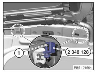
Special tool 72 1 210 for collecting rivet heads.
Shank (1) of special tool is flexible and can be adapted to the relevant body contours.
NOTE: Insert butyl in the collecting tray (2) to secure rivet heads and prevent them from falling out.
Insert special tool 72 1 210 through bore hole in body next to attachment points.
Position special tool from rear on rivet head in cavity.
NOTE: A second person will be needed to help hold the special tool on the rivet head during the driving-out operation.
Make sure collecting tray is correctly fitted on rivet head.
Drive out stem with hammer and 6 mm punch.
Carefully feed special tool out of body so that rivet head does not fall out of collecting tray.
NOTE: If the rivet falls out of the collecting tray into the side frame when the special tool is fed out, this area must be generously filled with foam.
For details of procedure for filling cavities with foam, see further operations.
Use cavity preservation for foam filling.
Cavity foam can also be used if necessary.
Fit tube to foam can.
Push the hose in through the pillar holes.
Fill cavity with a filling material.
WARNING: Empty foam can completely onto cardboard and after hardening dispose of foam and can in residual waste.
Can may burst if not completely emptied.
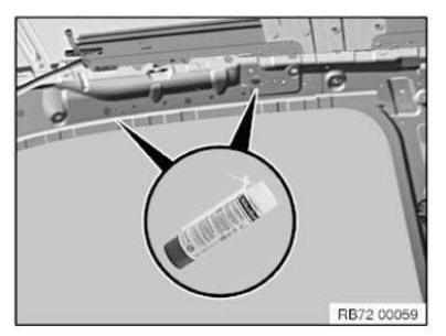
Overview of rivet gun: Riveting of gas generator housing and holders for folding pack with rivet gun.
The interchangeable head is changed for the different work operations.
Riveting of gas generator housing with:
- 17/36 nosepiece and short shank
Riveting of holders for folding pack: - 17/40 nosepiece and long shank
Safety at work
Note national regulations.
1.0 Compressed air:
- Air guns must not be pointed at individuals. "Blowing off" the body with compressed air may lead to serious injury.
- The devices are not permitted to be cleaned with compressed air due to dust contamination.
2.0 Electrical systems/devices:
- Only perfectly functioning systems and devices may be used.
- Repairs on electrical systems and devices must only be performed by certified electricians.
3.1 Working with aluminum dust:
- Wear a fine dust mask.
- Only applicable to E52 and I01: Use explosion-proof exhaust extraction unit.
- Note national regulations.
3.2 Removing sealant.
- Hydrochloric acid is created when PVC sealing material is heated to temperatures in excess of 180 ºC.
- Remove PVC sealant with a rotating wire brush only or heat material with a hot air blower to maximum 180 ºC and remove with a spatula.
- Ensure that all enclosed areas are well ventilated or are provided with direct extractor facilities.
3.3 Arc welding and brazing solder:
IMPORTANT: The extremely bright arc during welding may cause serious injury to the eyes if appropriate protective measures are not taken.
- Use a welding screen suitable for the relevant welding method (metal active gas or metal inert gas).
- Separation of workbays with protective curtains.
- Use a welding-emissions extractor facility.
- The welder must wear protective clothing and gloves which are suitable for welding (i.e. flameproof).
- A fire extinguisher must be located within reach of the welding area.
- Do not carry out any welding work in the proximity of a fuel tank e.g. when it is installed.
- Note national regulations.
3.4 Working with chemical products (adhesive, cleaning agents, fillers, etc.): Heed the manufacturer's material safety data sheets.
IMPORTANT: Handling chemical products may result in allergic skin and breathing reactions.
- Do not eat, drink or smoke while working with these products.
- Avoid direct contact with eyes and skin.
- Wear safety goggles, protective gloves and if necessary an apron.
- Ensure that all enclosed areas are well ventilated or extract fumes directly.
- Use a breathing apparatus with a suitable filter type when ventilation is insufficient.
- Wear impermeable protective clothing.
- Immediately change contaminated work clothing.
- After finishing work, thoroughly clean your hands and apply protective skin cream.
- Always keep an eye douche on hand, change the water regularly (once a month).
- Store bonding products in a secure cabinet only.
- Keep bonding products away from naked flames and other ignition sources.
- Protect bonding products against strong heat sources and direct sunlight.
- Note national regulations.
First Aid: If product comes in contact with eyes, immediately flush with running water for about 10-15 minutes.
Seek the advice of eye specialist.
In the event of skin contact and where applicable an allergic skin reaction, clean the affected areas immediately with soap and water and then apply silicone-free skin cream. If necessary, consult a doctor.
If an adhesive product is swallowed, rinse mouth/parts of mouth thoroughly with running water. Drink 1- 2 glasses of water. Do not induce vomiting. Consult a doctor.
After inhaling adhesive vapors ensure ample supply of fresh air. Stay calm. Keep air passages open.
Consult a doctor.
3.5 Repair work with carbon:
- Do not eat, drink or smoke while working with these products.
After finishing work, thoroughly clean your hands. Use protective hand cream.
- Fire, smoking and naked flames are forbidden.
- Wear work clothes, safety shoes, safety goggles and protective gloves.
- Only carry out grinding and cutting work with explosion-proof extraction.
Wear ear protectors.
- Wear a dust mask (minimum class FFP2).
- Avoid carbon dust contact with skin, eyes and clothing.
- Regularly clean the working area with a vacuum cleaner and wipe the surfaces with a damp cloth.
- Separate workbay by means of mobile partition walls or protective curtains.
Safety information for working on vehicles with automatic engine start-stop function (MSA)
WARNING: If the engine hood/bonnet contact is pulled upwards (workshop mode), the information "switch closed" is output. The automatic engine start-stop function is active.
An automatic engine start is possible.
Observe safety precautions when working on MSA vehicles. Before carrying out practical work on the engine, always ensure that the MSA functionality is deactivated so as to prevent automatic engine starting while work is being carried out in the engine compartment.
MSA function is deactivated by:
- Deactivate MSA by means of button (1) in passenger compartment
- Open seat belt buckle and driver's door
-
Open engine bonnet/hood and ensure that engine hood/bonnet contact is not in workshop mode
- Workshop mode
A = 10 mm - Basic setting (engine hood/bonnet open)
B = 7 mm
- Workshop mode
To make sure that the engine hood/bonnet contact is at the basic setting, if necessary press the hood/bonnet contact up to the limit position before starting work and slowly release.
When working with diagnosis tools:
- Observe instructions in diagnosis tool
Safety instructions for handling magnets
Precautionary measures are necessary when handling magnets in order to exclude any potential danger.
If the distance between the magnets falls below the minimum distance, the magnets will be abruptly attracted to each other. The brittle magnets will then collide with each other at high speed.
Very sharp splinters (similar to glass splinters) may then be chipped off.
Crush or cut injuries may also be caused.
Observe the manufacturer's safety data sheets.
WARNING:
- Danger of crush injuries
- Danger of injury due to splinters
- Danger of injury due to magnetic fields
Handling instructions
- Wear safety goggles and protective gloves.
- Persons with heart pacemakers must not use the magnets.
- Do not store any iron parts (tools, small parts) close to the magnets.
- Keep magnets away from magnetic data media (credit cards, memory cards).
- Do not machine the magnets.
- Keep the magnets away direct heat and naked flames.
- Do not eat, drink or smoke while working with these products.
Separating cut determination with a template
In the case of a partial replacement piece, a body component is cut at a point described in the repair instructions.
A template may be used for the exact position determination for the separating cut.
The template is made from the reinforcement plate and can be reused.
Carry over schematic diagram at the separation cut C-pillar to the relevant vehicle type.
Remove stud bolts (1).
Set bore holes Ø 4 mm at the positions of the removed stud bolts.
If applicable, place additional bore holes in the area of the edges.
Insert the template (1) into the new part (in direction of arrow) until it is flush (without gap).
Carry over the positions of the holes (2) to the new part.
Remove reinforcement plate again.
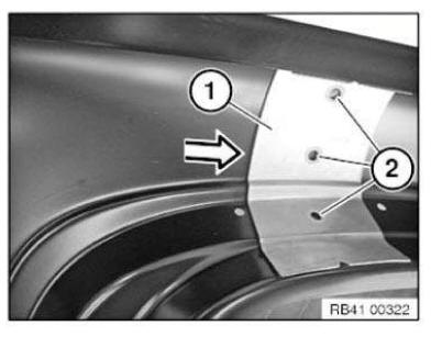
Connect marks (positions of holes) to the separating cut line (1).
Carry out the separating cut.
Tear and separate the separating cut on the vehicle according to the new part.
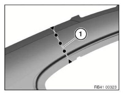
SETTING BLIND RIVET NUTS AND BOLTS
- Studs welded as standard are always replaced by blind rivet bolts.
- Drill holes (0.2 mm larger than the outside diameter of the blind rivet nuts or blind rivet bolts).
-
Blind rivet nuts and studs must have a special coating for anti-corrosion purposes (sourcing reference:
BMW Parts Department).
Use the blind rivet nuts and bolts supplied in the case of the manual riveting tool for steel only!
- It will no longer be possible to set a blind rivet nut if the drilled hole is too big. In this event, set a clip nut (sourcing reference: BMW Parts Department). This nut tightens itself automatically when screwed to the component.
- Insert blind rivet nuts or bolts and TIGHTEN DOWN WITH RIVET TOOL.
- Seal blind rivet nuts and blind rivet bolts with SEALANT D1 (risk of corrosion).
Soldering steel components
IMPORTANT: Comply with the following topics from "Body, General": Safety regulations .
Handling electrical system, electronics, airbags and restraint systems .
1. General information
- For repair cases the following procedure will implemented:
- Autogenous brazing solder
- The MIG soldering procedure is not used in repairs for strength reasons. MIG soldered/brazed seams used in standard production are replaced during repairs by MAG weld seams.
- Brazed areas from vehicle production are bonded following the same procedure.
2. Work materials
- Tube pack and torch (autogenous torch)
- Brazing solder
- Gas bottles (oxygen and acetylene)
- Welding goggles
3. Preparation
- Remove the paint and zinc layer in an area of approx. 30 mm around the seam to be soldered.
4. Implementation
- Execute brazed seam without overheating the solder and with low heat dissipation. If necessary, use heat protecting paste.
5. Subsequent treatment of brazed connections:
- Remove burnt residual zinc completely. Align and grind visible connection faces.
- Remove burnt paint with a stainless steel wire brush.
6. Notes on melting/tinning: Only applicable within the European Union! European used-vehicle regulations prohibit the use of tin containing lead in motor vehicles introduced after 01.07.2003! Even out unevenness smaller than 2 mm with filler according to painting handbook If an exceptional unevenness is larger than 2 mm, use METAL FILLER.
Only perform in visible areas of the outer skin and on the carrier support.
All areas which have covers on the vehicle are not to be processed.
Spot-weld bonding steel components
IMPORTANT: Comply with the following topics from "Body, General": Safety regulations .
Handling electrical system, electronics, airbags and restraint systems .
- Beginning with E65 the spot-weld bonding process is used to increase vehicle rigidity. In partial body areas, a 1-component adhesive is applied to the spot flanges and this is followed by resistance pressure spot welding. The adhesive is hardened only after the paint drying process (at approx. 180 ºC).
- In the case of repairs, adhesive is not applied to the spot flanges. The number of welding spots is doubled as a substitute for the omitted adhesive.
-
Minimum distance between welding spots (1) is 25 mm. Important! The minimum distance must not be
undershot! If there is not enough space for twice the number of resistance weld points, each non-made
resistance weld point must be replaced by a MAG weld seam (2). Length of a MAG weld seam = 20 mm.
Set the MAG weld seams at equal intervals distributed on the face.
- The following procedures are used as a substitute for spot-weld bonding:
- MAG welding (M etal A ctive G as welding)
- Resistance pressure spot welding (referred to in the following and in the repair instructions as spot welding).
-
Adhesive is not applied between the spot flanges on new parts in the case of 2- or multi-sheet joints.
Areas which cannot be reached by the spot-welding tongs can be joined by MAG plug welding. The number of welding spots is doubled as a substitute for the omitted adhesive.
- Exceptions (e.g. E65) are described in the relevant repair instructions. Apply welding spots to existing welding spots on new part. This is necessary because the adhesive between the spot flanges of the new part acts as an insulator.
CAUTION: Extract smoke and fumes during welding work.
Spray gun for cavity sealant
1.0 Delivery specification:
- Owner's Handbook
- Pressure reservoir spray gun (1) for cavity sealant
- Spray set, consisting of spray hoses: Angle nozzle (2) and round spray nozzle (3)
IMPORTANT: Prior to start-up read and familiarize yourself with the manufacturer's operating and safety instructions.
2.0 Start-up:
-
Open the pressure reservoir and insert the cavity sealant in the form of a 1-liter can.
Close the pressure reservoir.
- Connect the spray hose to the quick-release coupling.
- Connect the device to the compressed air supply.
Operating pressure 2-6 bar, max. 8 bar!
3.0 Operating principle:
NOTE: Unlike previous devices you can alter the spray pattern on this device with the air volume regulating screw (large knurled screw).
- Twisting the air volume regulating screw in decreases the air volume and thus reduces the formation of material mist.
This facilitates optimum working when preserving open components/surfaces.
- Twisting the air volume regulating screw out increases the air volume and thus increases the formation of material mist. (For closed cavities)
- The trigger has two settings.
1st setting - air discharge only.
2nd setting - air and material discharge.
- After finishing work, press the first setting to clean the spray hose with compressed air.
- Prior to storing, remember to twist the air volume regulating screw closed to reduce the risk of the material drying out.
- Prior to an extended period of non-use (2 weeks and more), clean the gun.
- To ensure that the spray hoses function properly, do not store them coiled up e.g. in the side member area! Store the spray hoses stretched out.
4.0 Application examples:
- Use the appropriate spray hoses for the different types of cavity and surface.
- Example - doors, lids and hatches: Spray hose with angle nozzle. Reduce air volume to keep the formation of mist low.
- Example - side members: Long spray hose with round spray nozzle. The air volume must be increased a little, depending on the type used.
- Basically, keep the formation of mist low to avoid fouling and unpleasant odors.
5.0 Safety instructions:
- Do not inhale spray mist.
- Use in well ventilated rooms only.
- Operating pressure max. 8 bar.
Stamping vehicle identification number (needle stamping unit)
Read and comply with GENERAL INFORMATION.
The needle stamping system 360 - VRM - BMW is required to stamp the vehicle identification number.
Order number: 81 43 2 155 736
The needle stamping system 360 tool set comprises:
- (1) Display
- (2) Mains adapter
- (3) Needle stamping unit
- (4) Connecting cable
- (5) Power cable
- (6) Compressed-air hose
NOTE: A compressed-air connection is also required.
- Operating pressure approx. 6 bar
- Use only dry, oil-free air
Necessary preliminary tasks:
- Remove TOP REAR CONNECTION
Procedure for additional vehicle identification number
- Cross through original vehicle identification number.
Detach filler neck (1) in upward direction.
Release screw (1).
Release screws (2) and (3) and remove holder for side wall.
1. = Original vehicle identification number (line 1).
Mark position lines (2) in accordance with specified dimensions/measurements.
Dimension a = 12 mm
Dimension b = 10 mm
Display input:
- Select Layout 5 with arrow button.
- Enter vehicle identification number with F10.
- Press "ENTER" button.
NOTE: With Layout 5 the vehicle identification number (line 1) is crossed through.
IMPORTANT: Perform stamping operation with position lines in advance on a test sheet.
Tape the hole (1) with a smooth adhesive tape (2).
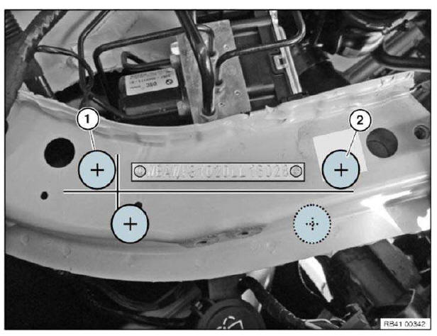
Move suction feet of needle stamping unit to positions (1) and (2).
NOTE: The contact surface for the suction cups of the needle imprint device must be dry and free of dust and grease!
Make sure the unit is resting securely in position. If necessary, adjust the height and position of the suction feet.
Press pushbutton (1) for vacuum pressure.
Then start stamping operation with pushbutton (2).
IMPORTANT: After completing the stamping operation, do not alter the position of the unit.
Do not switch off vacuum pressure.
Stamping second vehicle identification number
Display input:
- Select Layout 2 with arrow button.
- Press "ENTER" button.
NOTE: With Layout 2 the already entered vehicle identification number is stamped in line 2.
Start stamping operation with pushbutton (2).
Following layout functions are available:
| Layout selection | Vehicle identification number |
| Layout 1 | In line 1 |
| Layout 2 | In line 2 |
| Layout 3 | Turned through 180º in line 1 |
| Layout 4 | Turned through 180º in line 2 |
| Layout 5 | Cross through in line 1 |
| Layout 6 | Cross through in line 2 |
Straightening aluminum component on the outer skin
1.0 Prerequisites
The component must be replaced if there are cracks and it is neither possible to drill into the end of the crack, nor to weld it.
2.0 Recommended tools
- Only use tools specifically designed for aluminum repairs.
- Do not use tools and operating fluids that have already been used for steel repairs (e. g. grinding wheel). Danger of contact corrosion.
- Do not use any sharp-edged tools (notch effect).
3.0 Straightening outer skin
- "Cold" straightening: Press dents out from their center and smooth in an outwards direction with
gentle taps.
In the case of small, soft dents (hail and parking damage), this is also possible without damaging the paintwork. Special tools and a trained employee are needed.
- "Hot" straightening: Heat the component in the damaged area with a hot air blower to approx. 60 Â ºC. This significantly reduces the force that needs to be applied for straightening.
- Avoid notching and cracking.
- Avoid hardening and overstretching.
- Avoid heating and excess temperature the outer skin over large areas.
Straightening aluminum components in structure
-
Reshaping or heating extruded profiles and cast parts is not permitted!
Failure to comply with this requirement would have the following results:
In the case of reshaping, weld seams (E52) or bonded connections (E60, E61, E63, E64) tear in the surrounding area.In the case of reshaping, the material loses up to 40 % of its original strength.
In the case of heating, the material loses up to 40 % of its original strength.
The adhesive is destroyed at temperatures ≥120 ºC (E60, E61, E63, E64).
Extruded profiles and cast parts which show visible or measurable signs of deformation must be replaced.
Perform the check for deformation with the aid of the straightening system.
For optical testing, strip adjoining components in cases of doubt.
Extruded profiles are used in the E52 as engine supports, door posts, side members, etc.
Extruded profiles are used in the E60, E61, E63, E64 as engine supports.
Cast parts are used in the E60, E61, E63, E64, E70, E71 as spring supports.
-
Reshaping of extruded profiles and cast parts may only be used to achieve optimum joining of connection
faces (e.g. when bulkhead is damaged). Reshaped parts must be replaced.
Repairs which affect the attachment points of mechanical assemblies and chassis/suspension components must be carried out on the straightening bench. Use the vehicle-specific set of attachments set or vehicle- specific data sheet.
Straightening attachment supports and data sheets are also available for the top section, e.g.: door posts, soft top mounts, cowl panel, tailgate hinges, etc.
- Check windscreen and rear window apertures for curvature by inserting the original glass.
- Take the gap dimensions for doors, engine compartment lid and tailgate from the vehicle-specific gap dimension diagram.
- Exceptions on the E60, E61, E63, E64:
Carrier support and bulkhead may be straightened if they do not have any cracks, sharp-edged damage or holes. After repair work, check parts again for cracks.Examine adjoining adhesive flanges for peeling off. If necessary, seal and preserve with SEALANT.
Observe the frame reference dimension for the carrier support.
Any repairs to the bulkhead if cracked outside the approved scope of repair work are only permitted after consultation with and approval by BMW.
Straightening steel components in the structure
- High-strength and super-high-strength steel plates as a rule cannot be reshaped. Reshaping only serves as a preparatory measure to replacing the component in order to achieve optimal joining of the connection points.
-
Bearing body components such as e.g. engine supports, door pillars, side members etc. with deformations
which can no longer be returned to their original shape by "cold straightening" must be replaced.
Heating bearing body components for better reshaping is not permitted! Failure to comply with this requirement would result in a loss of original strength of up to 40 %. - The body must be anchored as follows for reshaping:
If using vehicle-specific/universal straightening attachment sets (Carbench/Celette/Car-O-Liner), it is necessary to secure the body additionally with 4 retaining clips to the spot flange of the entrance or to the 4 jacking points. The spot flange (if available) is to be preferred.If using universal electronic or mechanical straightening systems (Car-O-liner/Celette), it is necessary to secure the body with 4 retaining clips to the spot flange of the entrance or to the 4 jacking points. The spot flange (if available) is to be preferred. In addition anchor at least 2 points with the securing set.
Failure to comply with these instructions will result in damage to the body during reshaping in non- damaged areas. Vehicle-specific straightening attachments and universal mounts may be damaged.
-
Repairs affecting the mounting points of assemblies and chassis/suspension components must be carried
out on the straightening bench with the matching straightening attachment set or specification sheet for
the vehicle.
Straightening attachments and specification sheets are also available for the top section, e.g.: door pillars, convertible top mounts, cowl, rear lid hinges, etc.
- Check windshield and rear window apertures for curvature by inserting the original glass.
- Take the gap dimensions for doors, engine hood and rear lid from the vehicle-specific gap dimension diagram.
Straightening steel components on the outer skin
1.0 Recommended tools.
Only use those tools designed for steel repairs.
2.0 Straightening outer skin.
- "Cold" straightening: Press dents out from their center and smooth in an inwards direction with
gentle taps.
In the case of small, soft dents (hail and parking damage), this is also possible without damaging the paintwork. This requires special tools and a trained employee.
- In the case of damaged areas which are only accessible from one side, a repair system with welding can be used.
- Avoid cracking.
- Avoid hardening and overstretching.
- Prevent overheating small areas of the outer skin.
-
When the surface exhibits an unevenness no greater than 2 mm after straightening, putty compound
can be used to even out the area (see Painting Handbook).
Unevenness greater than 2 mm with metal putty.
NOTE: Only applicable within the European Union!
European used-vehicle regulations prohibit the use of tin containing lead in motor vehicles introduced after 01.07.2003!
- For high-security vehicle, note the special information in the repair instructions!
2.1 Straightening the wheel arch (rear side panel). Vehicles in which the wheel arch is not welded but bonded and bordered can be straightened.
This is possible in the following situations:
- Rear side panel (wheel arch) is not torn in the area of the bonding. Welding in this area is not permissible.
- The outer skin has not become separated from the outer wheel arch section.
In general, the following applies: When performing straightening work on the wheel arch, apply sealant to the inside. After straightening, the area must be primed and resealed with sealant D1. Protect from the inside using cavity preservation.
Touching up paintwork damage
These notes apply to paintwork damage on the body aperture that occurred when detaching bonded window glass.
To ensure long-term corrosion protection, it is absolutely essential to touch up damage to paintwork! The "BMW Color System" painting handbook forms the basis of these repair instructions and must be observed without fail.
Ground down damage to paintwork on body aperture and touch up with BMW multibase filler.
Grind larger areas or damage down to the bare sheet metal and coat with BMW multibase filler (layer thickness 30 to 40 μm).
Hardening time:
- With infrared, at least 10 minutes
- Without infrared for at least 60 ºC, at least 30 minutes
- Without infrared for at least 20 ºC, at least 24 hours
If a complete build-up of paint is required in the visible area:
- Tape off primed adhesive flange before applying top coat
IMPORTANT: Observe hardening time of BMW multibase filler otherwise a perfect bond cannot be guaranteed!
Use of materials in outer skin
The following illustration is a schematic diagram of all the body variants.
Apply this illustration to the relevant vehicle.
| Component | Vehicle | Material |
| (1) Side wall, front | F01, F02, F04, F10, F11, F18, F80, F82, F83 | Aluminum |
| F06, F12, F13, F15, F16 | Plastic | |
| F20, F21, F22, F23, F25, F26, F30, F31, F32, F33, F34, F35, F36 | Steel | |
| (2) Door, front | F01, F02, F04, F06, F07, F10, F11, F12, F13, F18 | Aluminum |
| F20, F21, F22, F23, F25, F26, F30, F31, F32, F33, F34, F35, F36, F80, F82, F83 | Steel | |
| (3) Door, rear | F01, F02, F04, F06, F07, F10, F11, F18 | Aluminum |
| F20, F25, F26, F30, F31, F34, F35, F36 | Steel | |
| (5) Engine compartment lid | F01, F02, F04, F06, F07, F10, F11, F12, F13, F15, F16, F18, F80, F82, F83 | Aluminum |
| F20, F21, F22, F23, F25, F26, F30, F31, F32, F33, F34, F35, F36 | Steel | |
| (6) Hardtop/roof | F01, F02, F04 | Aluminum |
| F06, F07, F10, F11, F13, F15, F16, F18, F20, F21, F22, F25, F26, F30, F31, F32, F33, F34, F35, F36 | Steel | |
| F82 | Carbon | |
| (7) Soft top compartment lid | F12 | Plastic |
| F23, F33 | Steel | |
| (8) Tailgate | F07 | Aluminum |
| F06, F12, F13, F82 | Plastic | |
| F01, F02, F04, F10, F11, F15, F16, F18, F20, F21, F22, F23, F25, F26, F30, F31, F32, F33, F34, F35, F36, F80 | Steel |
Vehicle identification number, general
In the event of repair 2 procedures are used, depending on the vehicle. Refer to the vehicle-specific repair instructions for the correct procedure.
1. General notes for stamped vehicle identification numbers:
The vehicle identification number is stamped with a special tool. There are different special tool numbers and stamping procedures for the various vehicles. Refer to the relevant repair instructions.
In repair work, the vehicle identification number is always stamped into a replacement vehicle identification number surface. The replacement surface is usually situated under the original VIN surface.
The IGEF number (bodyshell number) is omitted when the wheel arch is replaced.
In the event of component or body replacement by the BMW garages/workshops, clearly delimit the vehicle identification number at front and rear by stamping a + in place of the BMW badge.
If a VIN is stamped into the replacement surface in addition to the original VIN (e.g. if the original VIN has been tampered with), the following applies: The original VIN must be crossed out. To do so, stamp the letter I from the punch digits lengthways through the original VIN.
IMPORTANT: Do not use an angle grinder in conjunction with a cutting disk!
The protective film used as standard is omitted after the VIN has been manually stamped in. Paint area in accordance with BMW Painting Handbook. Ensure that layer thicknesses are small.
Observe national/country-specific regulations.
2. General notes for embossed vehicle identification numbers:
This procedure is used for all vehicles on which the vehicle identification number can not be stamped.
For the repair new parts with an embossed vehicle identification number can as a rule be ordered from the BMW Parts Department. If this is not possible, observe country-specific regulations.
The IGEF number (bodyshell number) is omitted when the wheel arch is replaced.
If a VIN is embossed into the replacement surface in addition to the original VIN (e.g. if the original VIN has been tampered with), the following applies: The vehicle-specific repair instructions describe the procedure.
The protective film used as standard is omitted after the VIN has been embossed. Paint area in accordance with BMW Painting Handbook. Ensure that layer thicknesses are small.
Observe national/country-specific regulations.
Welding in reinforcement plate (sheet steel)
In the case of a partial replacement piece, a body component is cut at a point described in the repair instructions.
A reinforcement plate is welded in to ensure sufficient strength.
Follow notes for WELDING STEEL COMPONENTS.
NOTE: The following graphics serve as general illustrations of reinforcement plate repair work. They are applicable to all sectional repairs.
Mark component in accordance with dimension A and cut.
Cut new part (1) in accordance with cut and if necessary adjust to fit with alignment bracket or universal mount.
Installation note: Maintain a distance of approximately one to no more than two material thicknesses at the severance cut to ensure welding with the reinforcement metal and enable more tolerant adjustment.
Clean inner and outer sides of connection faces (1) on new part and (2) on body.
Coat insides with welding primer.
Drill bore holes (1) and (2) at distance of 25 mm to each other.
Hole diameter approx. 8 mm.
Make reinforcement plate (1) from trim of new part.
If applicable, produce more reinforcement plates.
Length of reinforcement plates is min. 40 mm.
Coat reinforcement plates (1) and (2) on both sides with welding primer.
Push reinforcement plate (1) into component on body up to half way and plug-weld (3).
If applicable, adjust the new part (1) with the alignment bracket or universal tool and plug-weld (2).
MAG weld the joint (3).
Grind and clean weld seam and plug weld spots.
Only visible areas of the outer skin and on the carrier support must be tinned.
All areas which have covers on the vehicle are not to be tinned.
NOTE: Only applicable within the European Union!
European used-vehicle regulations prohibit the use of tin containing lead in motor vehicles introduced after 01.07.2003!
Welding steel components
IMPORTANT: Comply with the following topics from "Body, General": Safety regulations .
Handling electrical system, electronics, airbags and restraint systems .
1. General information
- The following procedures are used for repairs:
- MAG welding (M etal A ctive G as welding)
- Resistance pressure spot welding (referred to in the following and in the repair instructions as spot welding).
- Take the number and position of welding spots and MAG weld seams from the separated part.
Replace areas inaccessible to spot-welding tongs with MAG plug weldings at the same distance.
Diameter of bore holes for plug weldings 8 mm.
- In the case of emissions extraction, observe a minimum distance of 30 cm for MAG welding during the welding process. Otherwise the inert gas would be drawn off.
- Follow the equipment manufacturer's instructions for use.
2. Work materials
- MAG welding:
- Steel welder (see WORKSHOP EQUIPMENT).
- Steel welding wire - G3SI1 (SG2) or alternatively G4SI1 (SG3)
- Welding mask
- Gas bottle containing inert gas (82 % argon, 18 % CO2)
- Resistance pressure spot welding:
- Spot-welding apparatus (see WORKSHOP EQUIPMENT).
- Safety goggles
3. Preparations for MAG and spot-welding
-
Remove the paint coating in an area of approx. 30 mm around the weld seam or spot.
- The zinc layer underneath must be removed during the MAG welding method.
- It is not necessary to remove the zinc layer underneath during spot-welding.
- Remove the paint coating on the reverse side of the weld seam or spot.
- Contaminants will otherwise enter the weld pool via the root of the weld seam.
- An insufficient electron flow prevents an optimum spot-weld joint.
- Coat all metal overlaps and weld spot flanges with welding primer.
- To determine the optimum electrode contact force for spot-welding, carry out spot-weld shear tests on sample sheet metal.
- In order to keep the electron flow short during MAG welding on the body, you must if possible attach the ground terminal directly to the component to be welded.
4. Welding
- During MAG welding, the weld gap must be kept as small as possible. The larger the weld gap, the lower will be the strength of the joint.
- During spot-welding, the sheet metal flanges to be joined must be placed as close together as
possible without gaps.
The larger the gap, the lower will be the strength of the joint.
Minimum distance between welding spots 25 mm.
5. Subsequent treatment of welded connections:
- When grinding a weld seam, do not grind thin the base material next to the seam.
- After joining, clean all weld seams and spots with a stainless steel wire brush.
- Remove burnt paint with a stainless steel wire brush.
- All welded connections sealed off with body sealing compound in original condition must be primed and sealed off again thoroughly after repairing. Replace damaged or removed anti- drumming layers.
Working with 2-component PU cavity foam
Properties of cavity foam:
- 2-component PU foam, solvent-free.
- Excellent flow capacity, enabling complete sealing of cavities.
- Good strength, preventing slipping in cavities.
- Low water absorption, preventing corrosion.
- Ideal for use as insulating and sealing compound
Information on dangers/hazards:
- Avoid eye and skin contact.
Wear protective goggles, solvent-resistant protective gloves and protective clothing.
- Do not inhale.
Apply in well ventilated rooms only.
WARNING: Application time after mixing: within 8 minutes!
- Completely empty open can after use.
-
Remaining amounts which are not used can cause the can to explode on account of a chemical reaction
(buildup of heat)!
Alternatively, cool the can containing the non-removed remaining amount for several hours in cold water. - Do not eat, drink or smoke during this operation.
- Keep heat and ignition sources well away.
- Read the manufacturer's information on hazards/dangers (printed on the can) prior to application.
Application instructions:
- Use by date on can.
Do not use the spray can after the Use by date on the can has expired. After the Use by date the properties of the cavity foam will no longer meet the requirements of the BMW Group.
- Cavity sealing of repair area possible after an air drying time of 1 hour.
- Backing surface must be clean and free from dust, grease, oil and stripping agent.
- Application temperature at least 15 ºC. Optimally 20 ºC.
- Remove fresh, non-hardened PU foam with adhesive cleaner 208.
Sourcing reference: BMW Parts Service.
Hardened PU foam can only be removed by mechanical means (machine).
- Excess, hardened PU foam can be disposed of as residual waste.
Cans which are not entirely empty and unused whose Use by date has expired are classed as hazardous waste.
Observe country-specific waste-disposal regulations.
- Observe the manufacturer's application instructions (printed on the can).
IMPORTANT: Foam expands many times over as it sets (change in volume).
- Setting takes approx. 30 minutes. Mechanical processing (e.g. drilling, cutting, etc.) is then possible.
Workshop equipment (BMW and mini vehicles)
Minimum workshop equipment requirements in order to ensure the correct and expert performance of body repairs: The tools listed below must be used .
Repair stage 1:
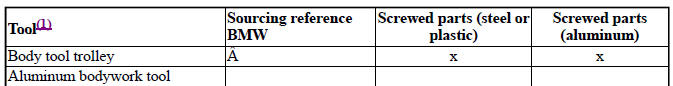
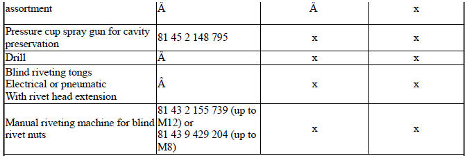
(1) Sourcing reference BMW Workshop Equipment Catalogue
Repair stage 2:
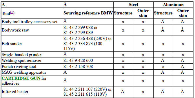
(1) Sourcing reference BMW Workshop Equipment Catalogue
In addition, the repair stage 1 tools are required.
Repair stage 3:
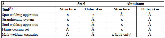
In addition, the repair stage 1 and 2 tools are required.
IMPORTANT:
In vehicles from model year 2001, higher-tensile and high-tensile steels are used in certain areas.
It is essential to check whether the spot-welding apparatus used conforms to the technical requirements of the currently recommended welding sets.
The use of technically obsolete equipment may have serious consequences for the structure of the vehicle (e.g. in the event of a crash). In the end, this can result in safety and product liability risks which cannot be calculated.
Use and restrictions:
Definition of recommendation:
All currently recommended spot welding sets comply according to the latest information with the requirements relating to reliable welding of today's and future BMW Group vehicles. A spot welding unit will lose its recommendation as soon as tests with materials and material combinations designated for future use in BMW Group vehicles return negative results (see Table Group 1). All previous application before the withdrawal of the recommendation shall remain unaffected.
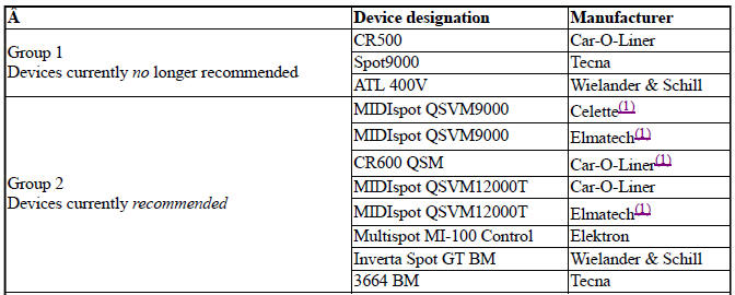
(1) no longer produced
Application options and restrictions of above devices.
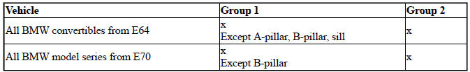
NOTE: April 2012
All BMW and MINI vehicles not mentioned can be repaired with the equipment of Group 1 and Group 2.
 Body corrosion protection
To comply with the six year warranty against rust, specially selected waxes
and additives produce an elastic,
temperature-proof,
corrosion inhibit ...
 Support members
...
Other materials:
BMW X3 (F25) Service & Repair Manual > HVAC: Cabin air filter
NOTE: Manufacturer's terminology for this filter is Microfilter.
REMOVAL & INSTALLATION
Replacing microfilter for interior ventilation
Turn toggle (1) through approx. 90º and remove cover (2) towards front.
Remove microfilter element (1).
Replacing microfilter for interior ventilatio ...
