BMW X3 (F25) Service & Repair Manual: Support members
- Replace entrance for front left door
- Replace sills, left
- Replacing engine support in front of wheel arch, left
- Replacing engine support with left wheel arch in front of bulkhead
- Replacing the carrier support before the wheel arch on the left
- Replacing the carrier support before the wheel arch on the right
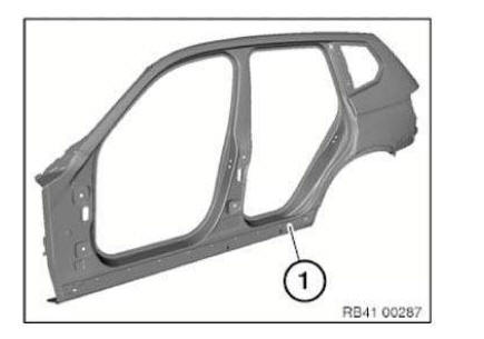
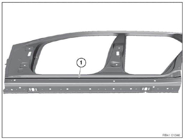
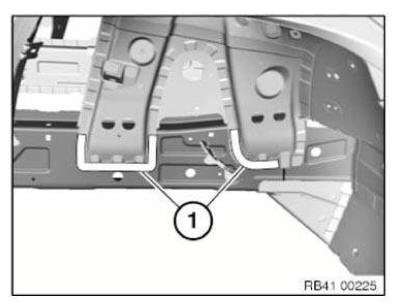
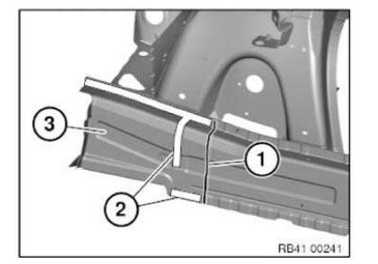
Replace entrance for front left door
Observe procedure for REPAIR STAGE 3.
Read contents of BODY, GENERAL.
Following new body parts are required (refer to OVERVIEW OF CONSUMABLES):
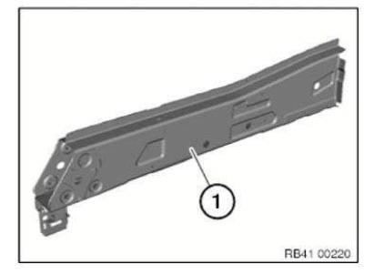
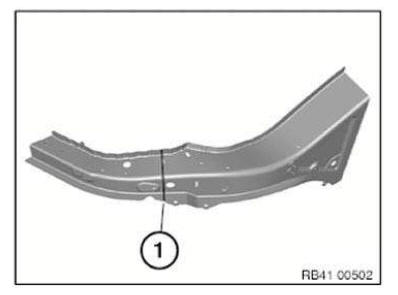
- (1) A-pillar with entrance
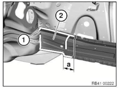
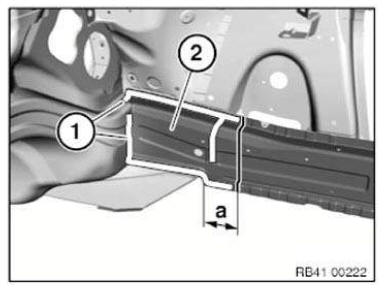
Mark severance cuts in accordance with specified dimensions and cut.
IMPORTANT: Cut outer panel only for following severance cuts.
Dimension a = approximately 380 mm in front of Ø 20 mm hole.
Dimension b = approximately 360 mm before separating cut a.
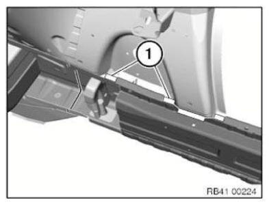
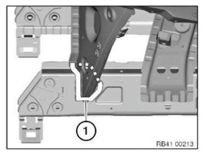
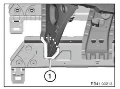
Open welded connections in areas (1).
Installation note: Mark new part in accordance with severance cuts on vehicle and cut.
Weld in REINFORCEMENT PLATES at severance cuts.
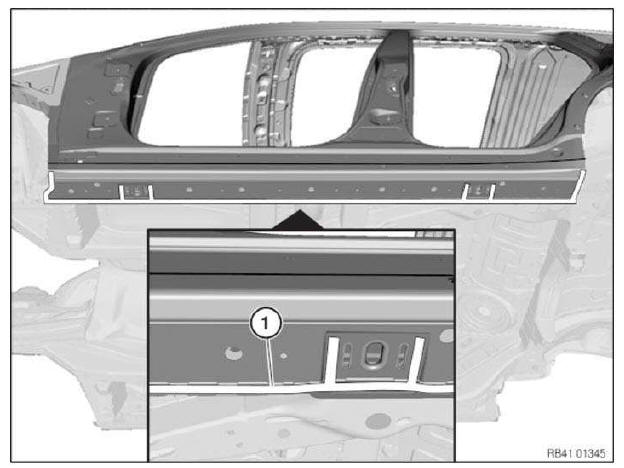
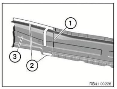
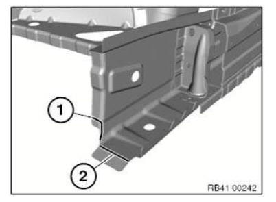
Replace sills, left
Procedure OBSERVE repair stage 3! Read contents of BODY, GENERAL.
Use only approved SPOT-WELDING APPARATUS for repairs! Following new body parts are required (see OVERVIEW OF CONSUMABLES):
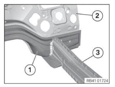
- (1) Outer side frame
Removal
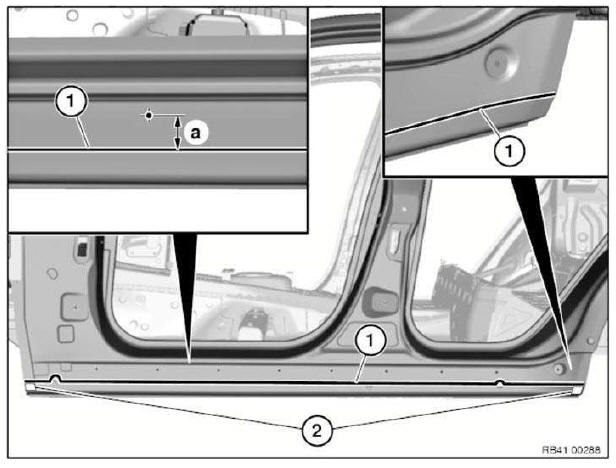
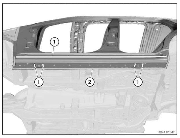
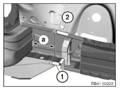
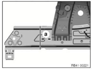
Mark severance cut (1) in accordance with dimension and cut.
IMPORTANT: Cut outer panel only.
Measurement a = approx. 40 mm from center point of 8 mm dia. hole.
Open welded connections in areas (2).
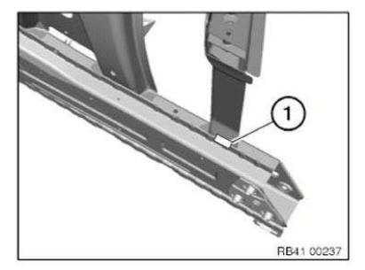
Open welded connections in area (1).
Remove sill.
New part preparation
Mark severance cut (1) on the new part according to vehicle + 20 mm extra material and cut.
Adjust new part to fit and secure.
Prepare new part for plug-weld in areas (1).
In area (2) prepare new part for spot-weld.
Remove new part and deburr holes.
Installation
Install new part and weld.
REPLACING ENGINE SUPPORT IN FRONT OF BULKHEAD ON RIGHT
Operation is identical to REPLACING ENGINE SUPPORT IN FRONT OF BULKHEAD ON LEFT.
REPLACING ENGINE SUPPORT IN FRONT OF BULKHEAD, LEFT
Observe procedure of REPAIR STAGE 3.
Read contents of BODY, GENERAL.
Use only approved SPOT-WELDING APPARATUS for repairs.
Place vehicle on straightening bench.
The following body new parts are required (refer to OVERVIEW OF CONSUMABLES)
- (1) Engine support
Removing the engine support
View of inside engine support.
Mark severance cut in accordance with dimension and cut.
Dimension a = approx. 110 mm from engine support edge.
Open welded connections in areas (1).
Remove partial section (2).
Mark severance cut in accordance with dimension and cut.
Dimension a = 140 mm from cross brace bulkhead.
IMPORTANT: Cut outer metal panel only.
Open welded connections in areas (1) and (2).
Open welded connections in areas (1).
Open welded connections in area (1).
Open welded connections in areas (1) and remove engine support.
New part preparation
Mark severance cut (1) in accordance with vehicle and cut.
Open welded connections in areas (2).
Remove metal section (3).
NOTE: The metal section (3) is needed to close the engine support.
Mark severance cut in accordance with vehicle and cut.
Adjust new parts to fit with alignment bracket or universal mounting.
Prepare REINFORCEMENT PLATES at severance cuts.
Installing engine support
Install new parts and reinforcement plates with alignment bracket or universal mount and weld.
NOTE: The bulkhead cross member (1) is filled with low-flammable cavity foam.
In case of smoke formation, stop the welding procedure and cool the welded area with compressed air if applicable.
- (2) Bulkhead
- (3) Engine support
MAG-weld new part in area (1).
Length of weld seam approx. 15 mm.
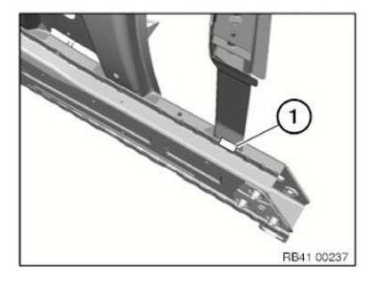
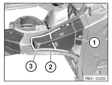
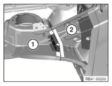
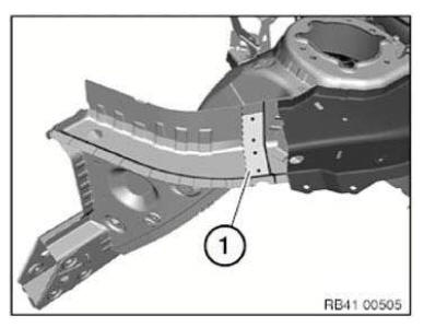
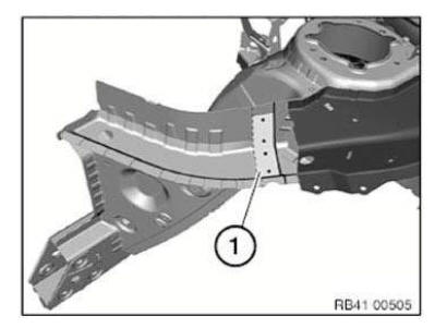
Replacing engine support in front of wheel arch, left
Follow procedure for REPAIR STAGE 3.
Read contents of BODY, GENERAL.
Use only APPROVED SPOT-WELDING APPARATUS for repairs.
Place vehicle on straightening bench.
Following new body parts are required (refer to OVERVIEW OF CONSUMABLES):
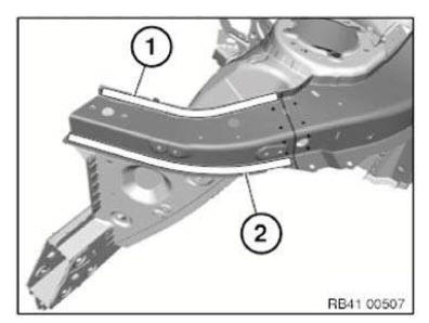
- (1) Engine support, front
Removing the engine support
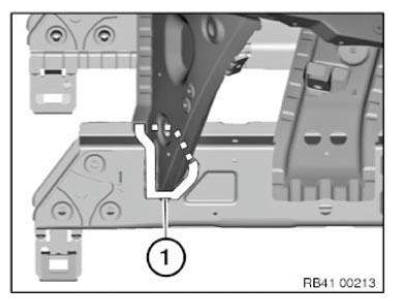
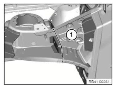
Open welded connections in area (1).
Mark severance cut in accordance with Dimension a and cut.
Dimension a=85 mm before wheel arch edge.
Remove section of engine support.
NOTE: Shown without carrier support for purposes of clarity.
Preparation of new part: Mark severance cut on new part in accordance with vehicle and cut.
Prepare REINFORCEMENT PLATE at severance cut.
Adjust new part to fit with alignment bracket or universal mount.
Installing engine support
Install new parts and reinforcement plates with alignment bracket or universal mount and weld.
MAG-weld new part in area (1).
Length of weld seam approx. 15 mm.
REPLACING ENGINE SUPPORT IN FRONT OF WHEEL ARCH, RIGHT
Operation is identical to REPLACING ENGINE SUPPORT IN FRONT OF WHEEL ARCH ON LEFT.
REPLACING ENGINE SUPPORT WITH FRONT RIGHT WHEEL ARCH IN FRONT OF BULKHEAD
Note the specific procedure with regard to the vehicle identification number (if necessary, order new body part with the vehicle identification number).
Operation is identical to REPLACING ENGINE SUPPORT IN FRONT OF BULKHEAD ON LEFT.
Replacing engine support with left wheel arch in front of bulkhead
Observe procedure of REPAIR STAGE 3.
Read contents of BODY, GENERAL.
Spot-weld bonding is used on this vehicle. Observe specific procedure .
Use only approved SPOT-WELDING APPARATUS for repairs.
Place vehicle on straightening bench.
Following new body parts are required (refer to OVERVIEW OF CONSUMABLES):
- (1) Wheel arch, front
- (2) Outer wheel arch carrier support
- (3) Carrier support end plate
- (4) A-pillar bulkhead
- (5) Shaped part, wheel arch carrier support (not shown)
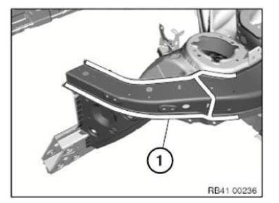
Removal of engine support with wheel arch
Mark severance cut (1) roughly as pictured and cut.
Open spot-welded adhesive joints in area (2) Open welded connections in area (3).
Release metal section from cavity sealing (4) and remove.
NOTE: Separating cut (1) is only required for removal.
Mark severance cut (1) as pictured and cut.
IMPORTANT: Cut outer metal panel only.
Open welded connections in areas (2).
Remove carrier support end plate metal section (3).
Mark severance cut (1) as pictured and cut.
Open welded connections in area (1).
Open weld joint in area (1).
Mark severance cut (1) in accordance with dimension and cut.
Dimension a = 110 mm from engine support edge.
Open welded connections in area (1).
Remove partial section (2).
Mark and cut severance cut (1) at a distance of approx. 25 mm to bulkhead cross member (2).
Open welded connections in areas (3).
Remove engine support with wheel arch.
NOTE: New part is installed with overlap in area of severance cut (1).
New part preparation
Release the applicable welded connections and remove metal sections that are not needed from the new wheel arch.
Mark severance cut (1) in accordance with vehicle and cut.
Open welded connections in areas (2).
Remove metal section (3).
NOTE: The metal section (3) is needed to close the engine support.
Perform severance cut (1) according to illustration.
Carry out severance cut (2) in accordance with severance cut on vehicle + 15 mm extra material.
Mark further severance cuts in accordance with vehicle and cut.
Prepare REINFORCEMENT PLATES at severance cuts.
Adjust new parts to fit with alignment bracket or universal mounting.
Adjust the new A-pillar bulkhead (1) in the area of the reinforcement plate (2).
(The new A-pillar bulkhead is set onto the reinforcement plate)
Installation of engine support with wheel arch
Apply sealant to new CAVITY SEALING of wheel arch carrier support.
Install new parts and reinforcement plates with alignment bracket or universal mount and weld.
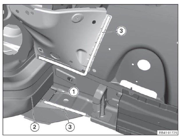
Weld the new part to the body in the areas (1) and (2)!
NOTE: The bulkhead cross member (1) is filled with low-flammable cavity foam.
In case of smoke formation, stop the welding procedure and cool the welded area with compressed air if applicable.
- (2) Bulkhead
- (3) Engine support
Weld new components in area (1) additionally.
REPLACING ENTRANCE FOR FRONT RIGHT DOOR
Operation is identical to replacing FRONT LEFT DOOR ENTRANCE.
REPLACING RIGHT SIDE SILL
Operation is identical to replacing LEFT SIDE SILL.
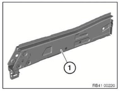
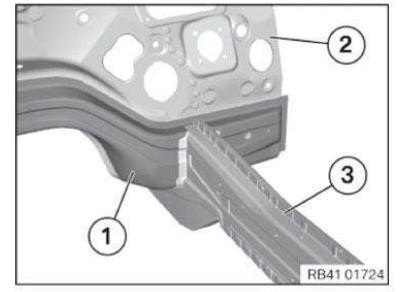
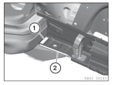
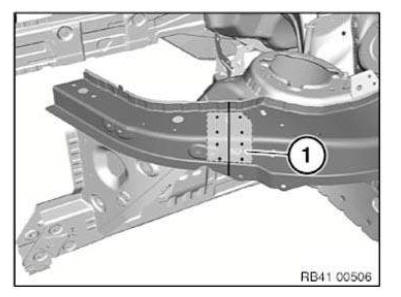
Replacing the carrier support before the wheel arch on the left
Read contents of BODY, GENERAL.
Follow procedure for REPAIR STAGE 2.
STRIP DOWN vehicle.
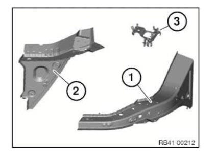
The following new body parts are required (refer to OVERVIEW OF CONSUMABLES):
- (1) Outer wheel arch carrier support
- (2) Carrier support, inner wheel arch section
- (3) Holder DSC (right side of vehicle only)
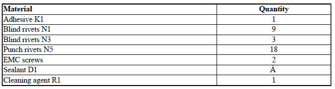
Following CONSUMABLES are required:
Removing carrier support
Open welded connections in area (1).
Right side of vehicle only:
Open weld joint in area (1).
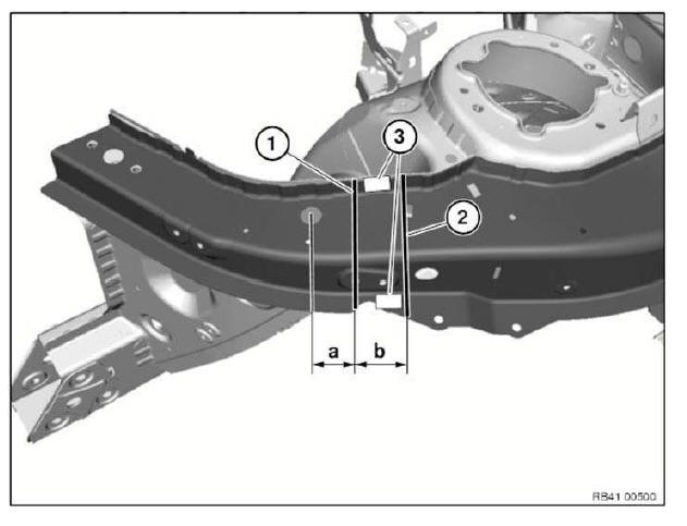
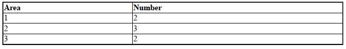
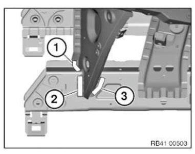
Mark severance cuts in accordance with specified dimensions and cut.
IMPORTANT: Fully sever the carrier support at severance cut (1)!
Only sever outer panel at severance cut (2)!
Dimension a = approx. 40 mm from bore hole Ø 20 mm.
Dimension b = approx. 50 mm from severance cut (1).
Open welded connections in areas (3).
Remove carrier support sections.
New part preparation
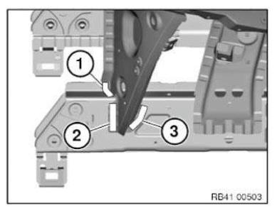
Mark new part in accordance with severance cut on vehicle (1) + 20 mm extra material and cut (2).
NOTE: Install new part overlapping in area of severance cut.
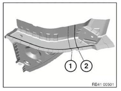
Mark new part in accordance with severance cut on vehicle and cut (1).
For the severance cut, create a REINFORCEMENT PLATE (welded) from the trim of the new part.
Adjust new parts with add-on parts to fit and secure.
In areas (1) to (3), introduce Ø 6.8 mm bore holes for blind rivets N1.
In areas (1) and (2) introduce one Ø 6.8 mm bore hole for blind rivets N1.
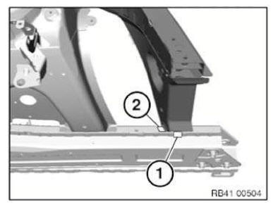
Prepare area of overlap (1) for plug-welding.
Prepare area of reinforcement plate (1) for plug-welding.
Right side of vehicle only: Fit DSC (1) holder.
In areas (2), introduce three bore holes Ø 4.2 mm for blind rivets N3.
Remove new parts and deburr bore holes.
IMPORTANT: Structure bonding! OBSERVE preparation of bonding surfaces.
Installing carrier support
Clean all bonding surfaces with cleaning agent R1.
Apply adhesive to bonding surfaces.
Install new parts with add-on parts and rivet with blind rivets.
Plug-weld in area of overlap (1).
At severance cut additionally set 4 metal active gas weld seams each with a length of 1 cm.
Install and weld reinforcement plate in area of severance cut.
Clean bonding surfaces with cleaning agent R1.
Apply adhesive to bonding surfaces, and adjust and fix new part.
In areas (1) and (2), rivet each new part with 9 punch rivets N5.
In area of severance cut, weld new part and reinforcement plate.
IMPORTANT: Risk of damage to adhesive area! Avoid applying excessive heat to the neighboring adhesive areas!
NOTE: Do not seal new parts in adhesive rivet areas (1) and (2).
After hardening of adhesive, in areas (2) and (3) install one EMC SCREW in each case.
Replacing the carrier support before the wheel arch on the right
Note the specific procedure with regard to the vehicle identification number (if necessary, order new body part with the vehicle identification number).
Operation is identical to REPLACING CARRIER SUPPORT IN FRONT OF WHEEL ARCH ON LEFT.
STRIPPING OPERATIONS - REPLACING CARRIER SUPPORT IN FRONT OF LEFT WHEEL ARCH
NOTE: Owing to the different engine variants and equipment specifications, not all the components are taken into consideration.
The following list basically represents the removal sequence.
- Disconnect battery earth lead (61 20 900 )
- Remove bumper trim (51 11 156 )
- Remove front panel (41 33 039)
- Remove front underbody protection assembly (51 47 490 )
- Remove front side panel (41 35 081)
- Remove front wheel arch cover (front section) (51 71 038 )
- Remove intake silencer housing (INTAKE SILENCER )
- Partially release left wiring harness


Other materials:
BMW X3 (F25) Service & Repair Manual > Suspension: Front control and suspension elements
REMOVING AND INSTALLING COMPLETE LEFT OR RIGHT SPRING STRUT (EDC)
NOTE: Work is identical to Removing and installing front spring strut .
REPLACING FRONT LEFT OR RIGHT SPRING STRUT (EDC)
Special tools required:
31 3 340
31 3 341
31 3 355
33 0 040
31 0 040
WARNING:
Prior to each u ...
